Gradient Background with Blue and Green Accents

RF Fundamentals: The Engineer's Reference

For engineers working with high-power RF systems — 1 W to 100 kW and higher 

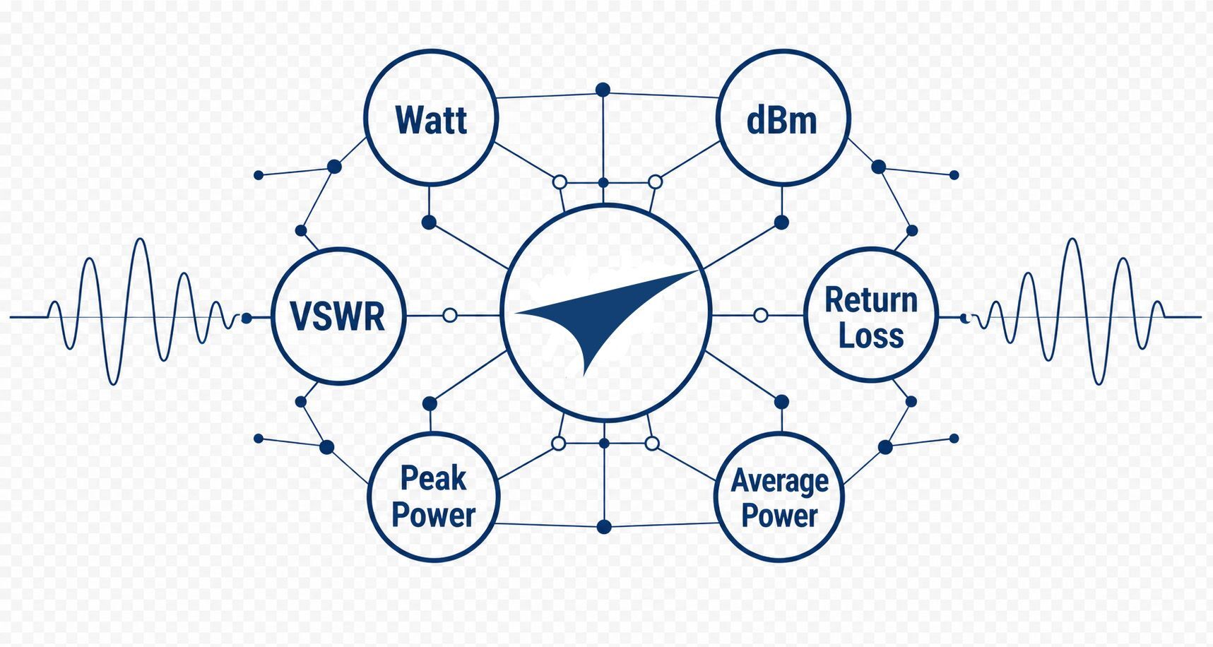
Dark Blue Tech Dashboard with Watt dBm VSWR Metrics
blue-bkgd

RF Power Measurement: The Complete Guide

Everything you need to understand forward power, reflected power, VSWR, signal types, and accurate RF measurement — from fundamentals to field application. 

What is RF?

 Radio frequency (RF) refers to electromagnetic frequencies used to transmit energy wirelessly, spanning from 3 Hz to 300 GHz. At these frequencies, alternating electrical currents radiate as electromagnetic waves capable of propagating across short distances or around the globe. 

RF is the foundational technology behind everyday wireless systems - communications, radar, satellite, and medical devices — but at high power levels, the stakes and complexity rise sharply, driving the most demanding applications in military, public safety, semiconductor manufacturing, broadcasting, scientific research, and industrial processing.

Understanding RF behavior — how signals propagate, attenuate, reflect, and interact with the physical environment — is essential for anyone deploying, maintaining, and troubleshooting high-power RF systems in the field. 

 With more than 80 years of experience in RF power measurement and transmission, Bird Technologies defines high-power RF as systems operating from 1 watt to 100 kW and above, where signal integrity, accurate measurement, and system reliability are mission-critical. 


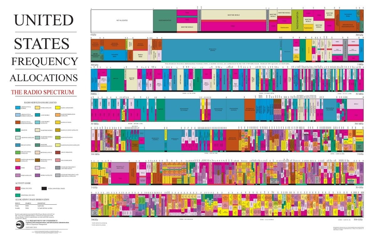
United_States_Frequency_Allocations_Chart_2016_-_The_Radio_Spectrum.pdf

RF Frequency Bands

The RF spectrum is divided into named frequency bands — each with distinct propagation characteristics, regulatory allocations, and real-world engineering trade-offs. For engineers working with high-power RF systems, frequency selection influences nearly every aspect of how systems are built, operated, and maintained in the field.

Understanding which band you're working in shapes everything from antenna design and power requirements to transmission line selection and measurement approach.

Knowing which band you're operating in establishes the context. Understanding how energy moves through the system is what makes that context actionable.

Explore the RF Frequency Bands and discover the engineering stories behind each one →

The RF Power Chain

Bird's framework for understanding how RF energy moves from source to result.

Every RF system, regardless of application or power level, follows the same fundamental path: RF energy is generated at a source, travels through a transmission path, and is delivered to a load that converts it into a useful result.

Bird Technologies calls this the RF Power Chain, a framework developed over 80 years of working with high-power RF systems across the most demanding applications in the field.

Understanding the RF Power Chain is essential for anyone responsible for deploying, operating, or troubleshooting high-power RF systems.

Each link in the chain introduces its own challenges: impedance mismatches, transmission losses, reflected power, and thermal stress. Measurement at critical points along the path is what separates a system that performs reliably from one that fails in the field.

The three diagrams below show how the RF Power Chain applies across common core application areas.

The RF Power Chain shows where energy travels. RF power measurement is how you know whether it's arriving. 

Typical RF Power Chain

Applications: Military · Utilities · Aviation · Rail · Maritime
Linear RF Power Chain: Transmitter (source) → Bird Sensor at Measurement Point 1 → Feedline → Bird Sensor at Measurement Point 2 → Antenna (load) → Radiated Signal (useful result). Transmitter Source Sensor MP 1 Feedline Sensor MP 2 Antenna Load Radiated Signal Useful result RF system component Bird measurement point (MP)


Land Mobile Radio RF Power Chain

Applications: Public Safety · Commercial LMR · Critical Infrastructure
Multiple transmitters (Transmitter 1, Transmitter 2, Transmitter 3+), each with a Bird Sensor (Measurement Points 1a, 1b, 1c), feed into a Combining System. After the Combining System, a Bird Sensor at Measurement Point 2 precedes the Feedline. A Bird Sensor at Measurement Point 3 sits before the Antenna (load), which produces Radiated Coverage as the useful result. Transmitter 1 Source Transmitter 2 Source Transmitter 3+ Source Sensor MP 1a Sensor MP 1b Sensor MP 1c Combining System Sensor MP 2 Feedline Sensor MP 3 Antenna Load Radiated Coverage RF system component Bird measurement point (MP)


Semiconductor RF Power Chain

Applications: Plasma Processing · Surface Modification · Industrial Coatings
RF Generator (source) → Bird Sensor at Measurement Point 1 (generator output) → Transmission Line → Bird Sensor at Measurement Point 2 (matching network input) → Matching Network → Bird Sensor at Measurement Point 3 (plasma chamber input) → Plasma Chamber (load) → Process Energy (useful result). RF Generator Source Sensor MP 1 Transmission Line Sensor MP 2 Matching Network Sensor MP 3 Plasma Chamber Process Energy Useful result RF system component Bird measurement point (MP)

From Estimation to Measurement - The RF Power Story

Before 1952, RF engineers had no direct way to measure transmitter output power. They measured AC input power, applied the manufacturer's published efficiency specification, and calculated an estimate. It was an indirect method that depended on assumptions rather than measurement - and if the transmitter wasn't performing exactly as specified, neither was the calculation.

Everything changed when J. Raymond Bird introduced the Model 43 Thruline® Wattmeter - the first instrument to measure forward and reflected RF power directly in the transmission path. It required no batteries, no external power, no slotted lines. The RF signal passing through it drove the measurement entirely. Engineers could finally see what their transmitters were actually doing, not what they were supposed to be doing.

More than one million Thruline® wattmeters have been sold worldwide. It remains in production today. Bird didn't just build a better instrument - Bird defined what RF power measurement means.

How the Bird Model 43 Defined RF Power Measurement →

Types of RF Power Measurements

RF power is expressed in two units that engineers use interchangeably. Watts describe absolute power - the rate at which RF energy flows through a system. dBm describes power logarithmically, relative to one milliwatt - the scale communications engineers prefer because it makes the enormous range of RF power levels easier to work with. A handheld radio operating at 5 watts is +37 dBm. A broadcast transmitter at 10 kilowatts is +70 dBm. Both units describe the same physical quantity. Knowing which your instrument displays - and how to move between them - is fundamental to field work.

Power levels vary dramatically by application. Land mobile radio systems typically operate below 250 watts. Semiconductor plasma systems range from 1 watt to 10 kilowatts. Broadcast, military, and industrial systems can reach tens or hundreds of kilowatts. Regardless of application, engineers face the same challenge: knowing how much of that power is actually reaching the load and how much is being lost along the way.

That challenge depends on choosing the right measurement type. Not all RF signals behave the same way, and not all power measurements answer the same question. A continuous wave transmitter, a digital radio system, and a pulsed radar signal each produce different measurement requirements - and selecting the wrong measurement type can produce results that look valid but misrepresent actual system behavior.

The table below covers the most common measurement types, which signals they apply to, and why each matters:


Measurement Type Best For Why It Matters
Average Power CW signals, continuous transmitters, general system verification Reflects overall power consumption and efficiency; most common measurement type
RMS Power Digitally modulated signals, variable-envelope waveforms Provides a true measure of signal power regardless of waveform shape
Peak Power Pulsed radar, pulsed RF systems, TDMA signals Captures instantaneous maximum power levels that average measurements would miss
Peak Envelope Power (PEP) SSB voice transmissions, amplitude-modulated signals Measures the power at the peak of the modulation envelope
Burst Average Power TDMA signals (P25, DMR, GSM) Measures average power during the active transmission burst only
Composite Power Multi-carrier systems, combined RF signals Measures total power of all signals present across a frequency band
Pulsed RF Power Radar, industrial RF, medical RF (MRI) Characterizes power during pulse on-time and duty cycle


A critical note on sensor selection: Traditional diode-based power sensors are designed and calibrated for CW signals. When used on digitally modulated signals with high peak-to-average power ratios - P25 Phase 2, DMR, LTE, OFDM - they produce systematic errors that look like valid readings. For these signals, true-average thermal power sensors or instruments with true-average detection are required. The Bird 4480A Digital Wattmeter uses true-average detection, making it the correct tool for modern digital radio systems. 


Related Article: Average Power vs. Peak Power — When Each Measurement Matters

The Engineer's Primary Diagnostic Tools

What RF Measurements Tell You

Once RF power can be measured, those measurements become the engineer's primary diagnostic tools. Every maintenance decision, from verifying transmitter output to identifying feedline loss or antenna mismatch, depends on interpreting a handful of key measurements correctly.

 What RF Power Measurement Captures

Every RF power measurement ultimately answers four engineering questions about any point in the RF Power Chain:

  • How much power is moving forward towards the load?

  • How much is being reflected back?

  • How much is actually being delivered?

  • How well are the source, transmission path, and load matched to each other? 

The answers to those four questions define the health of any RF system and they are only available through accurate, properly interpreted measurement.

VSWR and Return Loss — The Primary Field Diagnostics

Two measurements dominate field RF work: VSWR and return loss. Both metrics are derived from the same forward and reflected power measurements - and understanding both is essential for any engineer working across field and lab environments.

VSWR, or Voltage Standing Wave Ratio, expresses mismatch as a ratio. A perfect match is 1:1. A VSWR of 1.5:1 is generally considered acceptable for most land mobile and communications applications. Higher values indicate increasing mismatch and growing reflected power. VSWR is the language of the field - fast, intuitive, and immediately actionable.

Return loss expresses the same mismatch in decibels. A higher return loss value means less reflected power and a better-matched system - a 20 dB return loss indicates a well-matched system, while 6 dB indicates significant mismatch. Return loss provides finer resolution than VSWR at high match quality, making it the preferred metric in lab environments and precision applications.

A note on return loss convention

Return loss is expressed as a positive number in IEEE standards and most RF textbooks - and as a negative number on many field instruments and network analyzers. Both are correct, and the disagreement traces to two different mathematical traditions.

The classical RF definition computes the ratio of incident power to reflected power: because incident always exceeds reflected, the result is always positive. Higher is always better.

The S-parameter convention computes S11 - reflected voltage divided by incident voltage - which is always negative or zero for any matched load. Network analyzers display S11 directly, so engineers trained on network analyzers naturally think in negative values.

The two are related by a simple sign inversion: return loss (dB) = −S11 (dB). A return loss of +20 dB and an S11 of −20 dB describe identical performance.

Throughout this guide, Bird uses the negative convention - consistent with how most field instruments display return loss. When comparing specifications from different sources, always confirm which convention applies before interpreting pass/fail thresholds.

See the full explanation  -Is return loss expressed as a positive or negative number →

Impedance Matching — Why 50 Ohms Matters

Most high-power RF systems are designed around a 50-ohm impedance standard. When the source, transmission line, and load all present 50 ohms, maximum power transfer occurs and reflected power is minimized.  In practice, perfect matches are rare. The goal is to minimize reflected power enough that the system operates efficiently and safely. Deviations from this match caused by antenna damage, connector corrosion, feedline degradation, or equipment faults create the reflected power and elevated VSWR that measurement systems are designed to detect.

How to Read Forward and Reflected Power on a Bird Model 43 wattmeter →


What the Numbers Are Really Telling You

Interpreting RF Measurements

An accurate measurement is only half the job. Understanding what that measurement means — in context, at that location, on that system, on that day — is where field experience becomes essential. A forward power reading, a VSWR value, or a return loss figure is not a verdict. It is a data point. Interpreting it correctly requires knowing where in the RF Power Chain the measurement was taken, what the system's baseline looked like, and how current readings compare to historical trends.

Measurement Location Changes Everything

Where you measure determines what you see. A wattmeter connected at the transmitter output reports different values than one placed at the antenna feedpoint — particularly in systems with long or lossy feedlines. In a high-power system with significant cable run, the difference between forward power at the transmitter and delivered power at the antenna can be substantial. Before drawing any conclusion from an RF measurement, the first question is always: where in the system was this reading taken?

This matters most when interpreting VSWR and reflected power. In a system with lossy feedline, reflected power from a mismatched antenna is partially absorbed on the return trip through the cable. A meter at the transmitter may report lower reflected power — and a better-looking VSWR — than actually exists at the antenna. The cable is masking the problem by absorbing the evidence.

The Baseline Is the Reference

A measurement without a baseline is a number without meaning. A VSWR of 1.8:1 could represent excellent performance on one system and a developing fault on another — the difference is what the system measured at commissioning. Establishing baseline measurements at initial installation and after any component replacement creates the reference point that makes every future reading interpretable. Without a baseline, troubleshooting becomes guesswork. With one, a change in VSWR or forward power immediately points toward what has changed in the system.

Bird's RF troubleshooting guide recommends storing return loss, DTF, and cable loss traces at commissioning and comparing all future measurements against those stored baselines. The comparison — not the reading itself — is what reveals where the problem is.

VSWR Thresholds — What Acceptable Looks Like

In land mobile radio and most communications applications, a return loss of -14 dB or better is the widely accepted threshold for acceptable antenna system performance — indicating that roughly 96% of forward power is being delivered rather than reflected. VSWR values below 1.5:1 are generally considered good for most field applications. Higher values warrant investigation, and any sudden change from a known baseline warrants immediate attention regardless of absolute value.

Return loss provides finer resolution than VSWR at high match quality. Where VSWR values compress into a narrow range above 1.0:1, return loss in dB continues to differentiate cleanly — making it the preferred metric when small changes in match quality matter, such as in precision lab environments or high-stakes critical communication infrastructure.

Trending Over Time — What a Single Reading Can't Tell You

A single measurement is a snapshot. It tells you what the system looks like right now but nothing about the direction it is heading. Trending measurements over time — tracking forward power, reflected power, and VSWR at regular intervals — reveals gradual degradation patterns that a snapshot would miss entirely. A feedline absorbing moisture, a connector beginning to corrode, or an antenna slowly detuning due to environmental exposure will all show up as trends before they show up as failures. Remote monitoring systems that log continuous measurement data make this kind of trending practical even across large, distributed networks.

The Measurement That Looks Fine But Isn't

One of the most important interpretive skills in RF field work is recognizing when a measurement is telling you everything is fine — but the system is not performing. A lossy feedline can produce acceptable VSWR at the transmitter while the antenna is severely mismatched, because the cable absorbs reflected power before it reaches the meter. Acceptable VSWR paired with reduced coverage, lower field strength, or unexplained transmitter inefficiency is a signal to look deeper — not a reason to close the trouble ticket.


Related Article: How to Measure a Transmitter and VSWR with a Power Meter →

Related Article: RF Troubleshooting Guide — Return Loss, VSWR & DTF →

Knowing how to interpret a measurement correctly is essential. But even correct interpretation can't compensate for the variables that get between a reading and the truth. 

What Gets Between You and the Truth

Common RF Measurement Challenges

Accurate equipment and correct technique are necessary for reliable RF measurements — but they are not sufficient. In the field, a dozen variables can stand between a measurement and the truth about system performance. Recognizing these challenges is what separates engineers who trust their readings from those who get burned by them.

Hidden Line Loss — The Measurement That Flatters the System

Transmission line loss affects every measurement taken from the transmitter end of a feedline. As forward power travels toward the antenna and reflected power travels back, both are attenuated by cable loss. The result: a meter at the transmitter sees less reflected power than actually exists at the antenna — and reports a better VSWR than the antenna system deserves. In high-power systems with long feedline runs, this effect can be substantial. A system showing acceptable VSWR at the transmitter may be running a severely mismatched antenna that the cable is quietly masking.

What to watch for: acceptable VSWR at the transmitter paired with reduced coverage, lower field strength, or unexplained transmitter inefficiency.

Cable Degradation — The Problem That Hides in Plain Sight

Coaxial cables degrade over time. Moisture intrusion, UV exposure, physical damage, and connector fatigue all increase insertion loss gradually — often so gradually that no single measurement reveals the change. A degraded cable absorbs more power in both directions, which can actually make VSWR look better at the transmitter while the antenna receives less power than specified. The system appears healthy while performance quietly deteriorates.

Baseline measurements taken at commissioning are the only reliable way to detect this pattern. A cable showing increasing insertion loss over time relative to its commissioning baseline is a cable heading toward failure — even if current absolute readings look acceptable.

What to watch for: gradual changes in forward power or VSWR over time without a clear cause, or insertion loss measurements that exceed the cable's original specification.

Connector Problems — The Most Common Cause of RF System Failures

Loose, corroded, or damaged RF connectors are among the most frequent causes of poor RF system performance in the field. Connector problems introduce intermittent high VSWR, increased insertion loss, and intermodulation distortion — and they are particularly difficult to diagnose because symptoms often change with temperature, vibration, and physical handling. A connector that tests fine on a cold morning may fail under thermal stress by midday.

What to watch for: intermittent or variable readings that change with environmental conditions or physical contact with the feedline.

Antenna Mismatch — When the Load Isn't What the System Expects

An antenna that is damaged, detuned, incorrectly installed, or affected by ice loading or environmental exposure presents an impedance mismatch to the transmission system. The result is elevated reflected power and high VSWR — but only if the measurement is taken close enough to the antenna to see it. In systems with lossy feedline, the mismatch may be partially masked at the transmitter end. Distance-to-fault measurements using a cable and antenna analyzer can locate the exact point of mismatch within the feedline system.

What to watch for: elevated reflected power or high VSWR that wasn't present at commissioning, particularly after weather events, physical disturbances, or antenna system modifications.

Directional Coupler Errors — The Accuracy Floor Nobody Talks About

Every RF power measurement system depends on a directional coupler to separate forward and reflected power. The coupler's directivity — its ability to isolate the forward wave from the reflected wave — determines the accuracy floor of the entire measurement. A coupler with poor directivity allows forward energy to leak into the reflected measurement path, producing optimistic return loss numbers that mask real mismatch. Coupling factor also varies with frequency and temperature, introducing systematic errors that calibration must account for. A poor coupler can introduce more measurement uncertainty than the best power sensor can eliminate.

What to watch for: return loss readings that seem unusually good, particularly in high-VSWR environments like plasma chambers or severely mismatched antenna systems.

Digital Signal Measurement Errors — When the Wrong Sensor Lies to You

Traditional diode-based power sensors are designed and calibrated for continuous wave signals. When used to measure digitally modulated signals — particularly those with high peak-to-average power ratios like P25 Phase 2, DMR, or LTE — they can produce readings that differ significantly from true average power. The error is not random; it is systematic and repeatable, which makes it particularly dangerous because it looks like a valid measurement. For digitally modulated signals, true-average thermal power sensors provide accurate results where diode-based sensors do not.

What to watch for: power readings on digital systems that don't align with expected performance, coverage, or efficiency — particularly when using older diode-based measurement equipment.

Environmental Effects — What Weather Does to RF Systems

Temperature extremes, humidity, precipitation, and seasonal changes all affect cable performance, connector integrity, and antenna characteristics. Some effects are temporary — a VSWR spike during a rainstorm that clears when the weather does. Others are permanent — moisture that has entered a connector and begun to corrode the contact surfaces. Seasonal trends in VSWR or forward power readings are often the first visible sign of environmentally driven degradation before it becomes a field-visible failure.

What to watch for: readings that correlate with weather events or seasonal patterns, and any measurement that recovers on its own without intervention.


Going Deeper — RF Power: From Measurement to Meaning

The challenges above represent the most common obstacles between a measurement and the truth. But understanding them at a deeper level — knowing not just what to watch for but why the physics produces these effects and how experienced engineers diagnose them systematically — is what separates competent RF measurement from expert RF measurement.

Bird's white paper series RF Power: From Measurement to Meaning was written to close that gap. Drawing on 84 years of high-power RF field experience, the series covers:

Papers 1 and 2 available now. See link above. And for additional resources, see below:

Link: What Factors Affect RF Power Measurement Accuracy? →

Link: How Do Directional Couplers Impact RF Power Measurement Accuracy? →

Link: Common RF Interference Problems & How Spectrum Analyzers Solve Them →


Every measurement challenge covered above has a consequence. In high-power RF systems, those consequences extend beyond system performance — they extend to equipment protection and personnel safety. 

Protecting Equipment, Personnel, and Systems

RF Safety in High-Power Systems

High-power RF systems present two categories of safety concern that every field engineer must understand: protecting equipment from the electrical and thermal stress that mismatch and reflected power create, and protecting personnel from RF energy exposure. Both are engineering disciplines. Both depend on accurate measurement. And in high-power systems — where a moderate mismatch at 10 kilowatts generates the same reflected power as a severe fault at 100 watts — the consequences of getting either wrong are significant.

Equipment Protection — The First Line of Defense

The most immediate safety concern in high-power RF work is equipment protection. Reflected power, voltage stress, current stress, and thermal loading can damage transmitter output stages, stress combiners and circulators, overheat feedlines, and degrade loads — particularly when protection circuits are absent, disabled, or overwhelmed.

VSWR itself does not damage equipment. What damages equipment is the reflected power and resulting stress that mismatch creates inside amplifiers, transmission lines, matching networks, and output devices. The relationship between VSWR and reflected power is what matters:

VSWR Reflected Power (%) Field Interpretation
1.5:1 ~4% Healthy — normal operation
2:1 ~11% Warrants maintenance investigation
3:1 ~25% Fault condition — investigate before continuing operation
Above 3:1 >25% Treat as operational fault — immediate attention required

Many modern LDMOS and GaN solid-state amplifiers are designed to survive high mismatch conditions — some rated to withstand 3:1 continuously and 5:1 for limited periods with power foldback engaged. But surviving a mismatch is not the same as operating safely within it. Sustained operation above 3:1 VSWR — even with protection circuitry active — increases device junction temperatures, reduces efficiency, accelerates component aging, and places stress on circulators, combiners, and filters. At high power levels, the stakes scale accordingly:

At 3:1 VSWR, a 100-watt transmitter reflects approximately 25 watts. A 500-watt repeater reflects approximately 125 watts. A 10-kilowatt broadcast transmitter reflects approximately 2.5 kilowatts. At those levels, even a moderate mismatch generates substantial heat and stress on every component in the reflected power path.

A practical field standard: a 2:1 VSWR is not usually an emergency, but it warrants attention. A 3:1 VSWR is a fault condition. Above 3:1, assume something is wrong and investigate before returning the system to normal operation.

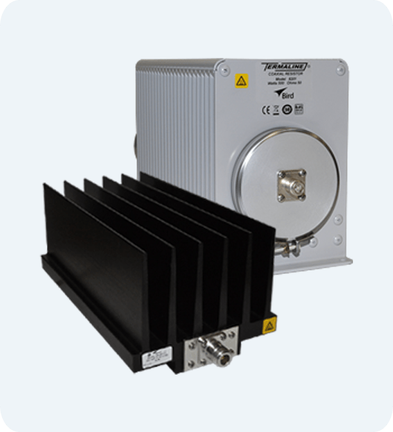
RF Loads — Controlled Power Dissipation for Equipment Protection

When RF energy cannot be delivered to its intended antenna or load — during testing, commissioning, transmitter tuning, or fault isolation — it must go somewhere. RF loads, also called dummy loads, provide a controlled, matched termination that absorbs RF power safely without radiating it. In high-power systems, selecting the correct load for the frequency range, power level, and duty cycle of the application is critical. An undersized or mismatched load in a high-power environment is itself a fault condition — one that can damage both the load and the transmitter driving it.

Bird RF loads are designed for high-power applications across Bird's core markets, providing stable 50-ohm terminations that protect equipment during testing and maintenance operations.

Human Exposure — Understanding RF Safety Requirements

In addition to equipment protection, engineers working in and around high-power RF systems must understand the requirements governing human exposure to RF energy. In the United States, RF exposure evaluations are governed by:

  • FCC regulations and OET Bulletin 65 — which establishes Maximum Permissible Exposure limits and methods for evaluating RF exposure from transmitters and antenna systems
  • IEEE Standard C95.1 — which defines exposure limits for human beings in electromagnetic fields
  • OSHA workplace safety requirements — which establish employer obligations for protecting workers from RF hazards

These standards define Maximum Permissible Exposure limits and provide methods for calculating safe working distances around transmitters and antennas. Engineers performing exposure evaluations need accurate system data — including transmitter output power, forward power delivered to the antenna, reflected power, antenna gain, feedline losses, and operating frequency. Reliable RF power measurements provide the verified system data that exposure calculations depend on.

Bird wattmeters, RF power sensors, and monitoring systems help engineers verify actual transmitter performance and document RF power levels throughout the system — providing the measured inputs that exposure analyses require.

Lockout/Tagout — Working Safely on Energized RF Systems

Before performing any maintenance, repair, or inspection on a high-power RF system, proper lockout/tagout procedures must be followed to ensure the system cannot be energized while personnel are working on it. RF energy at high power levels is invisible, silent, and capable of causing serious injury through thermal burns, RF shock, or arc flash at connectors and transmission line components. Lockout/tagout procedures, combined with RF power measurement to verify that systems are de-energized before work begins, are the standard practice for safe high-power RF field work.

Field engineers should confirm zero forward power at the measurement point nearest the work location before beginning any hands-on maintenance — and should treat any unexpected reading as a live system condition until proven otherwise.

The Role of Measurement in RF Safety

Equipment protection and personnel safety in high-power RF systems both depend on the same foundation: knowing what the system is actually doing. Accurate forward power, reflected power, and VSWR measurements tell engineers whether equipment is operating within safe parameters, whether protection systems are functioning, and whether the actual RF environment matches the assumptions used in exposure analyses. In high-power RF work, measurement is not just a performance tool — it is a safety discipline.

Whether the goal is system performance, equipment protection, or personnel safety, every outcome depends on the same foundation: measurements you can trust. 

Calibration: The Foundation of Accurate RF Power Measurement

Accurate RF power measurement begins with accurate calibration. Every Bird wattmeter and power sensor is calibrated against standards that are traceable to NIST (National Institute of Standards and Technology), providing a documented, unbroken chain of measurement back to a verified national standard.

At the heart of Bird's calibration capability is high-power calorimetry, a primary measurement technique that determines RF power by precisely measuring the heat generated as RF energy is absorbed by a known load. Unlike secondary methods that compare one instrument against another, calorimetry measures power from first principles, giving Bird an independent primary standard rather than relying on another manufacturer's reference.

Bird operates one of the world's most accurate high-power calorimetric standards, achieving 0.08% accuracy. That precision forms the foundation of the published accuracy specifications for every Bird RF power measurement product.

For engineers, this means more than an impressive laboratory specification. It means confidence that the measurements used to commission, troubleshoot, and maintain RF systems are based on a proven, verifiable reference. In high-power applications, even small errors matter—a 2% error at 10 kW represents a 200-watt difference, potentially leading to incorrect system adjustments, reduced performance, or regulatory compliance issues.

To maintain that level of confidence throughout the life of an instrument, Bird's ISO/IEC 17025 accredited Service Center provides NIST-traceable calibration services that restore Bird instruments to original factory specifications and supply calibration certificates accepted by regulatory agencies, government organizations, and quality systems worldwide. 

The measurement infrastructure Bird has built over 84 years flows directly into the instruments engineers use in the field every day. 

Tools of the Trade

Working in RF demands measurement tools that can keep up with the unique characteristics of high-power systems — from verifying transmitter output power across a wide frequency range to diagnosing antenna system faults before they become communication failures.

Here are the Bird instruments most relevant to system installation, commissioning, and maintenance.

43-Series-Wattmeters_lightgrey-1

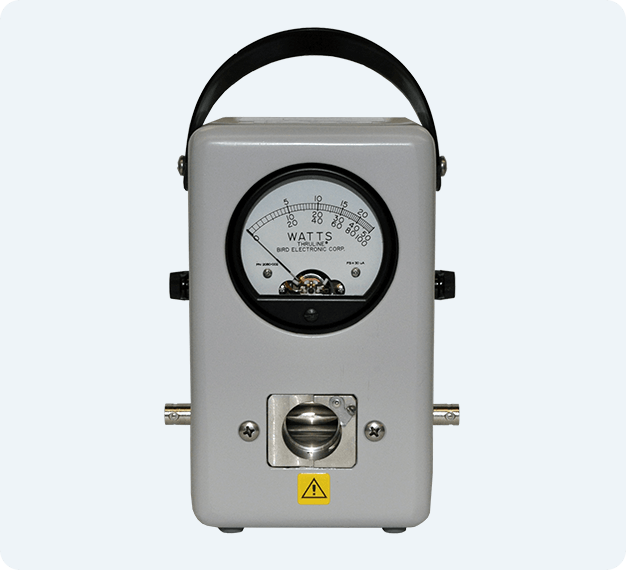
Bird Model 43 Thruline® Wattmeter

The instrument that defined RF power measurement. Introduced in 1952, the Model 43 measures forward and reflected power directly in the transmission line — no batteries, no external power required. Over one million units sold worldwide.

  • Interchangeable plug-in elements — wide frequency and power coverage
  • Measures CW signals — ±5% of full-scale accuracy
  • Ideal for traditional analog and CW applications
  • Still in production — supported by Bird's calibration service
hero-product-lightgrey-bg

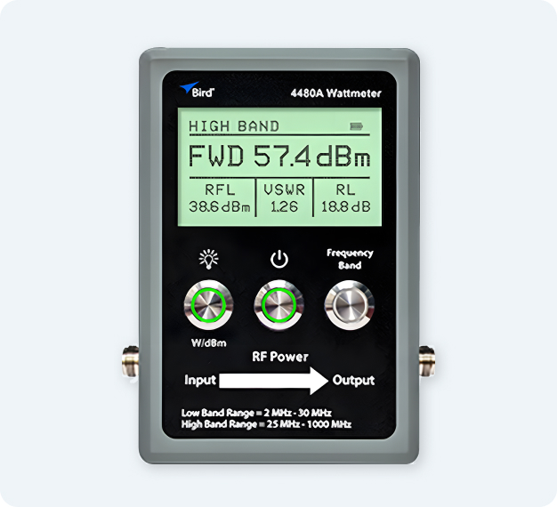
Bird 4480A Digital Wattmeter

The Thruline® measurement philosophy brought into the digital era. Element-free, with true-average detection for both CW and digitally modulated signals. Displays forward power, reflected power, VSWR, and return loss simultaneously.

  • 2 MHz – 1 GHz, no plug-in elements required
  • True-average power — accurate on P25, DMR, NXDN, TETRA
  • ±4% of reading accuracy
  • Reads in watts or dBm — direct digital display
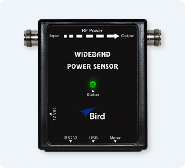
Wideband-Power-Sensor_lightgrey

Wideband RF Power Sensors

Broad frequency coverage in a single in-line sensor. Suited for lab environments, multi-band system testing, and field applications requiring wide-range power characterization.

  • 25 MHz – 4 GHz coverage
  • Up to 500 W power handling
  • Compatible with meters and external instruments
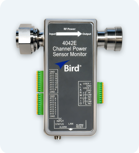
4042E-ptt-626x570

Remote RF Monitoring Systems

Continuous forward power, reflected power, and VSWR monitoring without on-site visits. Configurable alarms give NOC teams early warning of developing issues before they become failures.

  • Ethernet-connected — accessible from any network location
  • Configurable thresholds and alarm notifications
  • Reduces unnecessary truck rolls and response time
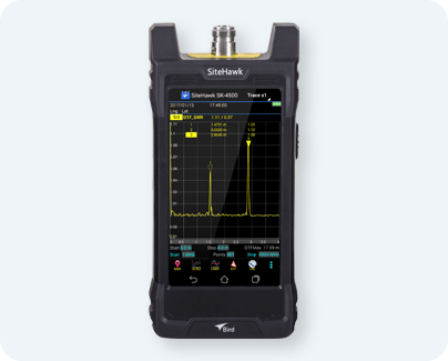
SK-4500-TC-blue

Cable & Antenna Analyzers

Measure return loss, VSWR, cable loss, and distance-to-fault. Establish commissioning baselines and locate faults in feedlines and antenna systems without removing components.

  • Handheld and field-portable
  • Distance-to-fault — locate faults without removal
  • Stores baseline traces for trend comparison
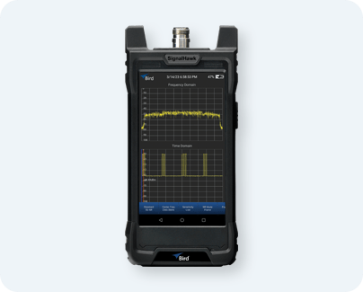
SH-75S-TC-spectrum-analyzer-blue

Handheld Spectrum Analyzers

Frequency-domain visibility into what's actually present on the air. Identify interference, locate unauthorized transmitters, characterize signal quality, and support system commissioning.

  • Handheld and field-portable
  • Real-time RF analysis across wide frequency range
  • Interference identification and signal characterization
500w_loads-blue

RF Loads & Terminations

Controlled 50-ohm terminations that safely absorb RF power during testing, commissioning, transmitter tuning, and fault isolation. Designed for high-power applications across Bird's core markets — with options covering a range of power levels, frequency ranges, and cooling methods.

  • High-power rated — matched to Bird's 100 mW to 80 kW range
  • Stable 50-ohm termination — protects transmitters during test
  • Multiple cooling methods available
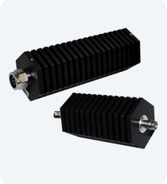
attenuators_group-blue

RF Attenuators

Precise, reliable control over signal strength for testing, troubleshooting, and protecting sensitive components. Bird attenuators reduce signal levels by a fixed dB value while safely dissipating RF power — preventing receiver overload, reducing reflections, and maintaining system performance in high-power environments.

  • Power handling from 2 W to 4,000 W
  • Attenuation values of 10, 20, 30, and 40 dB
  • Frequency coverage DC to 4 GHz
  • Multiple cooling methods available
FAQs

Frequently Asked Questions

What is RF power and how is it measured?

RF power is the rate at which RF energy moves through a system, expressed in watts or dBm. It is measured using a directional wattmeter or power sensor placed in-line with the transmission path — between the transmitter and the load. The sensor separates forward power (energy moving toward the load) from reflected power (energy returning from a mismatched load), providing the data needed to calculate delivered power, VSWR, and return loss. Bird Technologies introduced the first instrument to measure RF power directly in the field in 1952 with the Model 43 Thruline® Wattmeter — prior to which engineers could only estimate transmitter output by calculating AC mains power multiplied by transmitter efficiency.


What is the difference between forward power, reflected power, and delivered power?

Forward power is the RF energy traveling from the transmitter toward the antenna or load. Reflected power is the portion of forward power that is not absorbed by the load and travels back toward the transmitter — caused by an impedance mismatch. Delivered power is the net power actually transferred to the load: forward power minus reflected power. This is the power doing useful work. A system can show strong forward power while delivering significantly less than expected if reflected power or transmission line losses are high — a common source of confusion in the field.


What is VSWR and what does it tell me about my RF system?

VSWR, or Voltage Standing Wave Ratio, describes how well the impedance of the transmission line and load are matched. A perfect match is 1:1. Values above 1:1 indicate increasing mismatch and growing reflected power. In land mobile radio and most communications applications, VSWR below 1.5:1 is considered healthy, 2:1 warrants investigation, and 3:1 or above is typically treated as a fault condition requiring immediate attention. VSWR is one of the most widely used indicators of antenna system health in the field — fast, intuitive, and immediately actionable.


What is return loss and how does it relate to VSWR?

Return loss and VSWR both describe impedance mismatch but express it differently. Return loss is the ratio of reflected power to forward power expressed in decibels — a higher return loss value means less reflected power and a better-matched system. A return loss of -14 dB or better is the widely accepted threshold for acceptable antenna system performance in LMR applications. Return loss provides finer resolution than VSWR at high match quality, making it the preferred metric in lab environments and precision applications where small changes in match quality matter.


Is return loss expressed as a positive or negative number?

Both conventions exist, both are technically defensible, and the disagreement traces back to two parallel mathematical traditions in RF engineering that never fully reconciled.

The classical RF convention — positive return loss

In traditional RF and microwave engineering, return loss is defined as a loss — specifically, the fraction of incident power that was not reflected. Loss values in RF engineering are conventionally positive: cable loss is positive, insertion loss is positive, and return loss follows the same logic.

The formula is:

Return loss (dB) = 10 × log₁₀ (P_incident / P_reflected)

Because incident power always exceeds reflected power in any real system, this ratio is always greater than 1 and its logarithm is always positive. A return loss of 20 dB means reflected power is 100 times smaller than incident power. Higher numbers are always better. This is the IEEE definition and the convention used in antenna specifications, cable standards, and most RF engineering textbooks.

The S-parameter convention — negative return loss

S-parameters describe signal behavior in networks using voltage wave ratios. S11 — the reflection coefficient at port 1 — is defined as the ratio of reflected voltage to incident voltage:

S11 = V_reflected / V_incident

For any matched load, the reflected voltage is smaller than the incident voltage, so |S11| is less than 1. Expressed in dB, S11 is always negative or zero. A perfect match produces S11 = −∞ dB. A short circuit produces S11 = 0 dB.

Network analyzers display S11 directly — always as a negative number. Engineers who learned RF measurement through network analyzers carry that sign convention into every return loss discussion. When they say "return loss of −20 dB," they mean exactly what a classical engineer means by "return loss of +20 dB."

The mathematical relationship:

The two conventions are related by a simple sign inversion:

Return loss (dB) = −S11 (dB)

A return loss of +20 dB and an S11 of −20 dB are identical measurements expressed in two different conventions. The physics is the same. Only the sign differs — and the sign depends entirely on which ratio was computed: incident/reflected or reflected/incident.

Why instruments make it worse:

Different instruments follow different conventions without always stating which one they use. Network analyzers display S11 — negative. Cable and antenna analyzers vary by manufacturer and sometimes by firmware version. The Bird SiteHawk displays return loss as a positive number, consistent with the IEEE convention. A network analyzer from another manufacturer will display the same measurement as a negative number. Both are correct. Both are measuring the same physical quantity.

The practical rule:

When comparing return loss specifications from different sources, always confirm which convention applies before interpreting pass/fail thresholds. A specification stating "return loss better than −14 dB" and one stating "return loss better than 14 dB" describe identical performance. An engineer reading one convention while thinking in the other will interpret the threshold backwards — and may pass a system that should fail, or flag a system that is perfectly healthy.

Throughout this guide, Bird uses the negative convention — consistent with how most field instruments display return loss. Where specifications from other sources are referenced, confirm the sign convention before comparing.


Why does my VSWR look acceptable at the transmitter when my antenna system is actually degraded?

This is one of the most common and counterintuitive challenges in RF field work. Transmission line loss attenuates both forward and reflected power as signals travel through the cable. Reflected power from a mismatched antenna is partially absorbed on the return trip through a lossy feedline — so a meter at the transmitter sees less reflected power than actually exists at the antenna. A degraded cable can make a severely mismatched antenna look acceptable at the transmitter end. If VSWR looks fine but coverage is reduced or transmitter efficiency has dropped, investigate feedline loss before concluding the antenna is healthy.


Why shouldn't I place an RF power sensor directly at the load or "hang" it off the load?

This is a field practice mistake that experienced RF engineers recognize immediately. Placing a sensor too close to the load — or hanging it off the load without proper mechanical support — creates several problems. First, the sensor may be measuring in the near field of the load rather than in a stable transmission line environment, producing readings that don't reflect true system performance. Second, in high-power systems, thermal radiation from the load can heat the sensor body, introducing measurement errors as the sensor's internal components drift with temperature. Third, unsupported sensors place mechanical stress on connectors, which can cause intermittent contact, measurement errors, and connector damage over time. Always mount sensors in a stable transmission line section with adequate thermal separation from high-power loads.


How do heating effects affect RF power measurements?

Thermal effects are one of the most underappreciated sources of measurement error in high-power RF work. As RF power flows through a sensor, the sensor's internal components generate and absorb heat — and sensor accuracy specifications are typically given at a reference temperature. In high-power applications, heat from the transmission line, the load, or the ambient environment can shift a sensor's internal temperature enough to introduce measurement error. Best practice is to allow sensors to thermally stabilize before taking reference measurements, to ensure adequate airflow or cooling around sensors in continuous high-power applications, and to recalibrate sensors on a regular schedule — particularly in thermally demanding environments like semiconductor processing or high-duty-cycle broadcast systems.


What is the difference between average power and peak power — and when does it matter?

Average power is the mean RF energy delivered over time — the standard measurement for continuous transmitters and most field applications. Peak power is the instantaneous maximum power level, which can be significantly higher than average power in pulsed or burst transmission systems. The ratio between peak and average power is called the Peak-to-Average Power Ratio (PAPR). For CW signals, average and peak power are essentially equal. For pulsed radar, TDMA digital radio systems like P25 Phase 2 and DMR, and semiconductor plasma systems using pulsed RF, peak power can be substantially higher than average — and measuring only average power on these signals misses critical information about system behavior and equipment stress.


Can I use a diode-based power sensor to measure P25, DMR, or other digital radio signals?

Traditional diode-based sensors are designed and calibrated for continuous wave signals. When used to measure digitally modulated signals with high peak-to-average power ratios — like P25 Phase 2, DMR, LTE, or OFDM — they can produce readings that differ significantly from true average power. The error is systematic and repeatable, which makes it particularly dangerous because it appears to be a valid measurement. For digitally modulated signals, true-average thermal power sensors or instruments with true-average detection — like the Bird 4480A Digital Wattmeter — provide accurate results where diode-based sensors do not.


What is the difference between the Bird Model 43 and the Bird 4480A?

Both are Thruline® wattmeters that measure forward and reflected power directly in the transmission line. The Model 43 uses interchangeable plug-in elements to cover different frequency and power ranges and measures CW signals with ±5% of full-scale accuracy on an analog display. The 4480A is element-free, covers 2 MHz to 1 GHz, measures both CW and digitally modulated signals with true-average detection, displays forward power, reflected power, VSWR, and return loss directly on a digital screen in watts or dBm, and specifies accuracy at ±4% of reading. The Model 43 is the right choice for traditional CW applications. The 4480A is the right choice for modern digital radio systems including P25, DMR, NXDN, and TETRA. Full comparison →


How often should RF power sensors be recalibrated?

Calibration intervals depend on the application, operating environment, and power levels involved. In most commercial RF applications, annual calibration is standard practice. In high-power, high-duty-cycle, or process-critical environments — such as semiconductor plasma processing — more frequent recalibration may be required to maintain measurement confidence. Bird's ISO 17025 accredited service center provides NIST-traceable calibration for Bird sensors and wattmeters, restoring instruments to original factory specifications.


What is impedance matching and why does it matter in high-power RF systems?

Impedance matching is the process of ensuring that the source, transmission line, and load all present the same impedance — typically 50 ohms in high-power RF systems, or 75 ohms in broadcast and cable television. When impedances are matched, maximum power transfer occurs and reflected power is minimized. Even minor mismatches create reflected power — and in high-power systems, the reflected energy that is inconsequential at low power levels becomes a significant source of heat, equipment stress, and efficiency loss at hundreds or thousands of watts. Maintaining a good impedance match throughout the RF Power Chain is a fundamental requirement for reliable high-power system operation.


What causes high VSWR in an RF system?

High VSWR is caused by an impedance mismatch between the transmission line and the load. Common causes in the field include antenna damage or detuning, connector corrosion or mechanical damage, feedline degradation due to moisture intrusion or physical damage, equipment faults, and ice loading on antenna systems. In semiconductor applications, plasma ignition, process changes, and matching network drift can all cause VSWR to rise. Any sudden change in VSWR from a known baseline warrants investigation — particularly in high-power systems where elevated reflected power creates immediate stress on transmitter output stages and associated components.


What RF measurement equipment does Bird Technologies make?

Bird Technologies manufactures a comprehensive range of RF power measurement and test equipment for high-power RF systems operating from 1 watt to 80 kilowatts. The product line includes portable wattmeters (Model 43 and 4480A Digital Wattmeter), in-line wideband power sensors, cable and antenna analyzers (SiteHawk), handheld spectrum analyzers (SignalHawk), Ethernet-connected remote RF monitoring systems, RF loads and terminations, and calibration equipment. Bird products are designed for field, lab, and continuous monitoring applications across land mobile radio, public safety, utilities, military, broadcast, semiconductor, and industrial RF markets. Bird's measurement accuracy is traceable to NIST and supported by an ISO 17025 accredited calibration service center.


How does Bird Technologies ensure measurement accuracy?

Bird Technologies maintains calibration standards traceable to the National Institute of Standards and Technology (NIST). At the foundation of Bird's calibration capability is high-power calorimetry — measuring RF power by precisely quantifying the heat generated when RF energy is absorbed by a known load. Bird operates one of the most accurate high-power calorimetric standards in the world, achieving accuracy to within 0.08%. This primary standard flows directly into the accuracy specifications of every Bird measurement product and supports Bird's ISO 17025 accredited calibration service center.



 

RF Glossary

RF has its own vocabulary. If you encounter a term that needs defining, the RF Glossary covers more than 80 terms used across high-power RF measurement, transmission, and system performance. 

RF Fundamentals - Built for the Field

High-power RF systems demand more than technical knowledge. They demand measurement confidence — the certainty that what the instrument reads reflects what the system is actually doing, at every point in the chain, under every operating condition.

That confidence doesn't come from the instrument alone. It comes from the calibration behind it, the measurement discipline around it, and the 84 years of field experience that shaped both.

That is what Bird brings to every measurement.

Explore Bird's RF Power Measurement Solutions

Related Topics

Explore adjacent areas of RF system performance and testing:

  • Cable & Antenna Testing — Tools and techniques for verifying transmission line and antenna system integrity
  • Remote Monitoring — Continuous, real-time visibility into RF infrastructure health
  • Spectrum Analysis — Understanding the frequency domain for interference detection and signal characterization
  • RF Engineering Glossary - A complete reference of RF terminology used throughout this guide