RF power measurement accuracy is affected by impedance mismatch, heating and thermal drift, nonlinear effects, coupler directivity, insertion loss, and coupling factor variations. Each of these can introduce errors ranging from 1–2% in best-case conditions to 10–15% when left unchecked. Even with proper calibration, these hidden variables often determine whether your measurement is trustworthy or misleading. These errors don’t just frustrate engineers — they can lead to wasted test time, costly troubleshooting, and poor system performance.
Here are six of the most common factors that affect RF power measurement accuracy, and how you can control them.
1. Impedance Mismatch
Every RF system assumes 50 Ω, but in practice, connectors and cables rarely achieve a perfect match. Even small deviations reflect energy back toward the source and skew forward/reflected readings.
-
Best case: ~2% error
-
Worst case: >12% in high-reflection conditions
-
Tip: Use high-return-loss components, torque connectors properly, and measure return loss with a VNA.
2. Heating and Thermal Expansion
High-power RF generates heat — and heat shifts dielectric constants, resistances, and calibration curves.
-
Best case: <1% drift with compensation
-
Worst case: 5–8% error after extended high-power runs
-
Tip: Calibrate at operational power levels, not just room temperature.
3. Nonlinear Effects
At high fields, ferrites can saturate, dielectrics can shift, and connectors may even arc. These nonlinearities distort waveforms and reduce accuracy.
-
Best case: <2% error in CW
-
Worst case: 5–10% in pulsed/high-field systems
-
Tip: Verify linearity across the full range and avoid ferrite-based couplers for precision pulsed work.
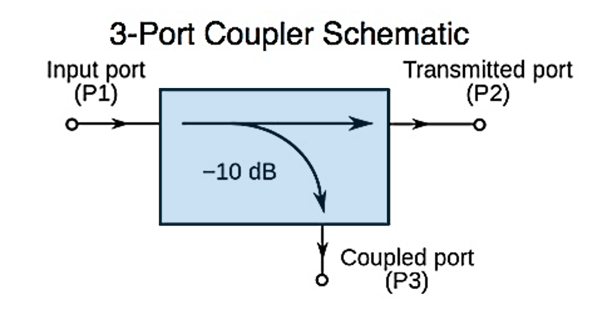
4. Directivity
Directivity defines how well a coupler separates forward and reflected signals. Poor directivity lets energy “leak” between paths, corrupting data.
-
Best case: 1–3% error with ≥40 dB directivity
-
Worst case: 10%+ error with <25 dB directivity
-
Tip: Always check directivity specs; high-reflection environments demand high-directivity devices.
5. Insertion Loss
Every extra adapter, cable, or coupler adds small losses that add up.
-
Best case: <1% error when corrected
-
Worst case: 3–4% when left unchecked
-
Tip: Simplify the path and account for known losses in calibration.
6. Coupling Factor Variations
Nominal coupling factors rarely stay exact. Drift, tolerances, and aging shift values, creating systematic bias in readings.
-
Best case: ±1% with factory calibration
-
Worst case: 5–6% if left uncorrected
-
Tip: Recalibrate on schedule, don’t assume stability.
Engineering Takeaway ⚡
Even with the right method, hidden variables can balloon error margins. Best-case accuracy is ±0.5–4%, but without control, errors can spike past 10–15%.
The good news: most of these sources are controllable with careful setup, recalibration, and component selection.
Katie Wright
An electrical engineer with more than 30 years of experience in RF Test and Measurement, Katie Wright specializes in high-power RF measurement, product strategy, and technical thought leadership. At Bird Technologies, she works closely with engineers and customers across the semiconductor, aerospace & defense, broadcasting, and industrial markets to translate complex RF technologies into practical engineering knowledge. Her work focuses on RF measurement accuracy, calibration, and helping engineers better understand the principles and applications behind high-power RF systems. A licensed amateur radio operator (KD8FAD), Katie brings both professional expertise and hands-on RF practice to everything she writes.


