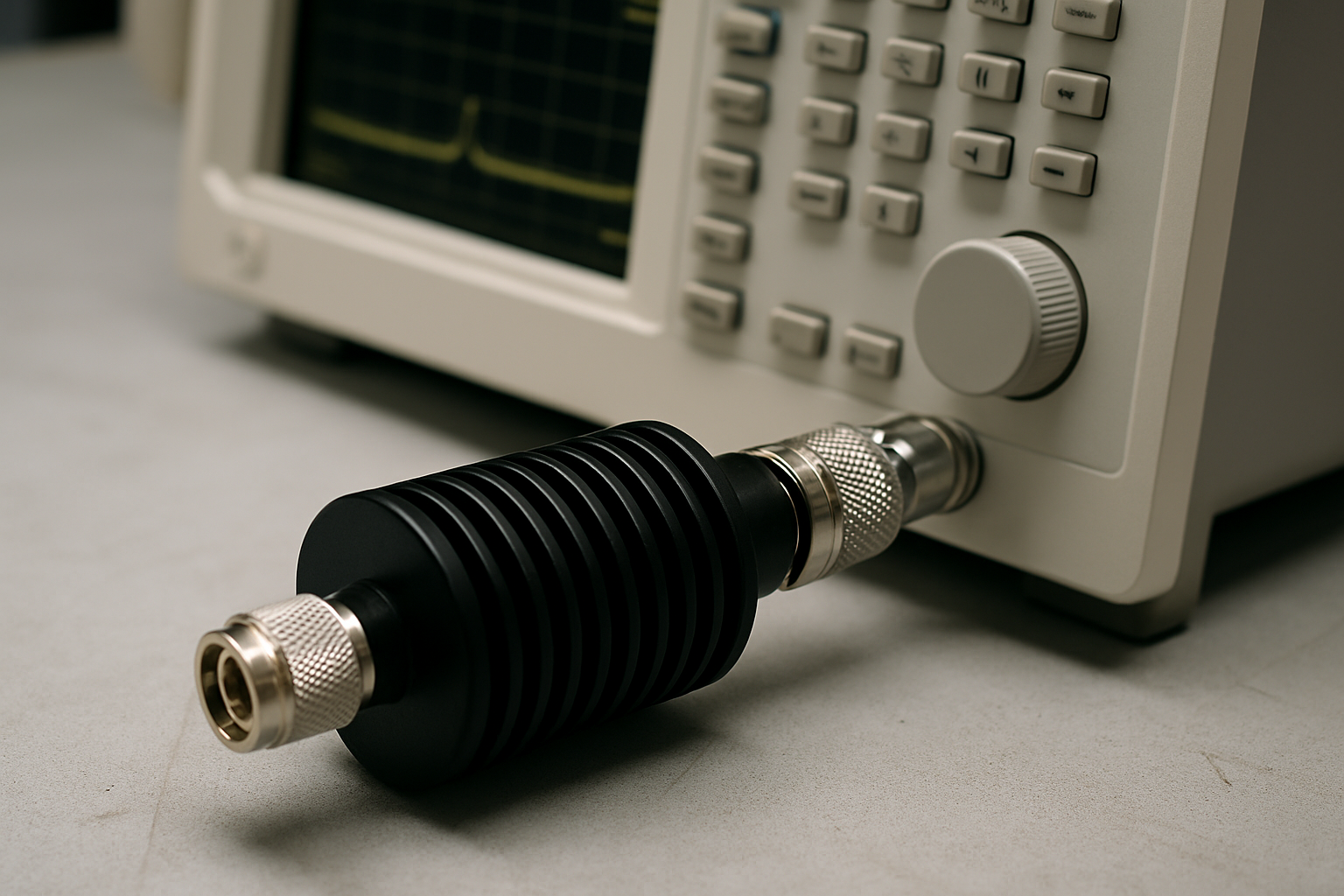
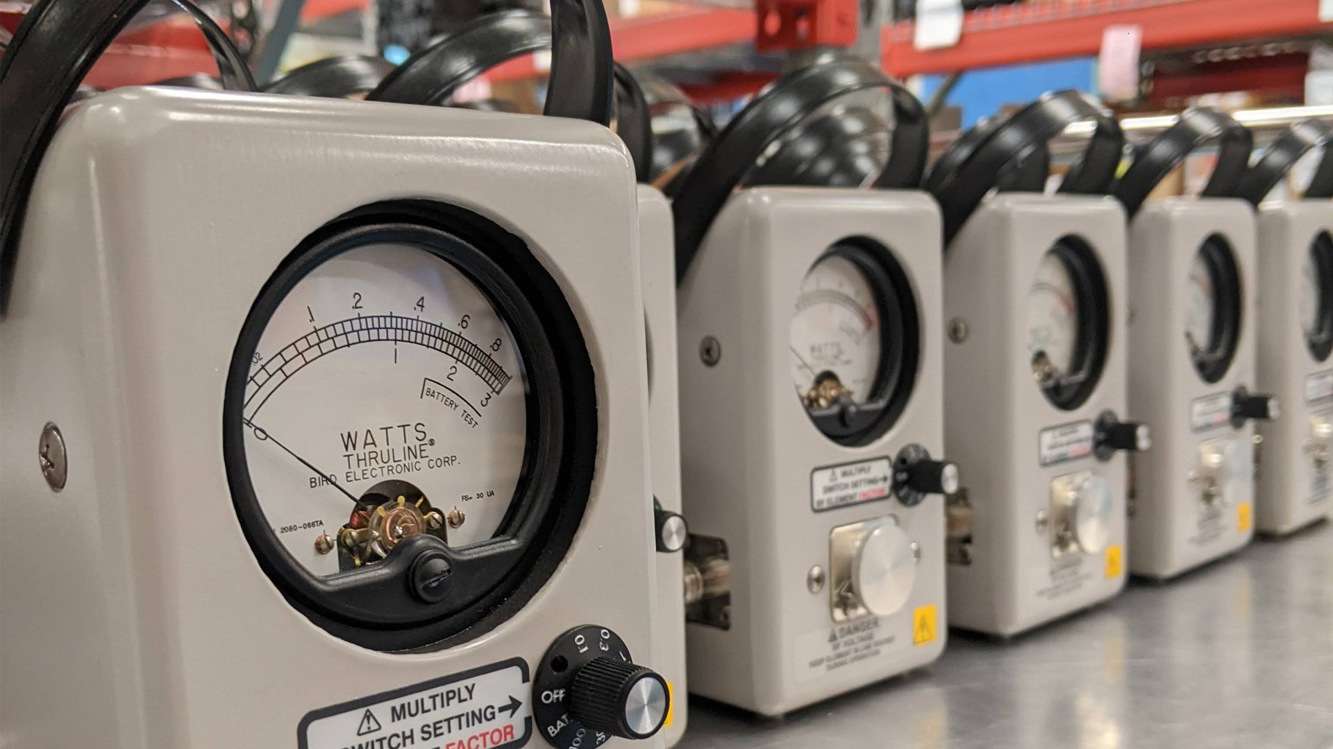
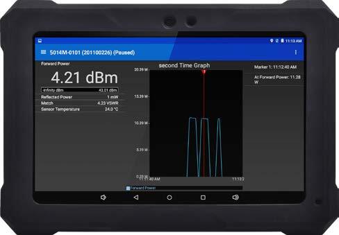
Oscilloscopes and spectrum analyzers can provide power estimates, but unlike purpose-built RF power meters, they lack factory calibration, traceable accuracy, and low measurement uncertainty. Dedicated RF sensors deliver repeatable ±0.5–4% accuracy, while scopes and analyzers often drift into ±10% or more, depending on setup.
That said, these instruments still offer engineers valuable visibility: oscilloscopes in the time domain, and spectrum analyzers in the frequency domain. Let’s break down how each method works, where they shine, and where they fall short.
Oscilloscope + Directional Coupler
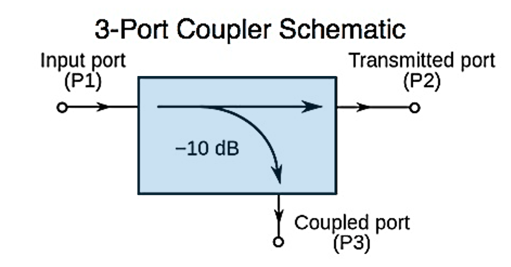
Oscilloscopes let you see RF signals in the time domain. When paired with a directional coupler, they provide insights that power meters can’t: waveform shape, rise and fall times, overshoot, jitter, and transient behavior.
How it works:
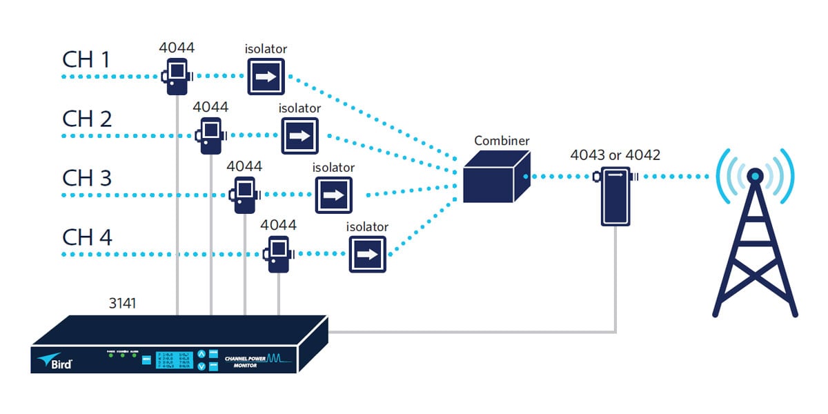
- A coupler samples a fraction of the RF signal.
- The sampled signal is routed into a high-bandwidth oscilloscope.
- Engineers analyze the waveform, and with calibration, extract power data.
Strengths
- Rich time-domain insight into pulse fidelity and distortion.
- Wideband capability — captures broadband and harmonic content.
- Flexibility: FFT analysis adds frequency-domain visibility.
Limitations
- Calibration is everything: scalar-only calibration often yields ±10–15% error.
- Bandwidth constraints: limited by oscilloscope front-end and ADC resolution.
- Fragility: high-power signals must be carefully attenuated to avoid damage.
- Complexity: accurate calibration requires VNAs or reference sources.
Engineering takeaway ⚡
Oscilloscopes are unmatched for visibility, but unless they are vector-calibrated, they should not be relied upon for precise RF power accuracy.
Spectrum Analyzer + Directional Coupler
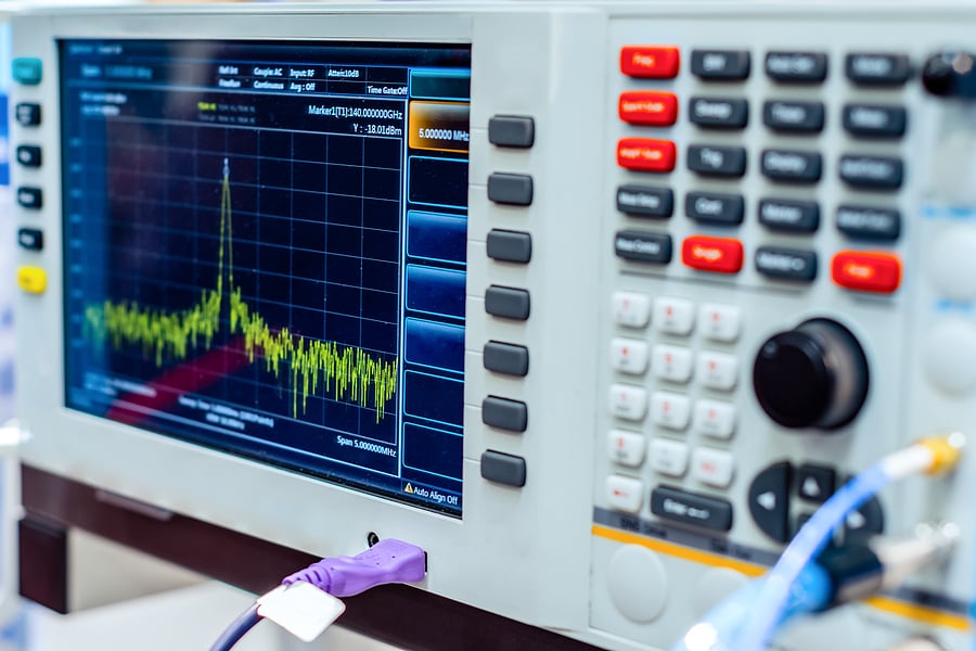
Spectrum analyzers, by contrast, excel in the frequency domain. They reveal how RF power is distributed across carriers, harmonics, and noise. When paired with a coupler, they can also estimate total power.
How it works:
- A coupler samples a portion of the RF signal.
- The analyzer measures the signal’s power spectral density.
- Engineers integrate over bandwidth or focus on carriers to calculate power.
Strengths
- Frequency-domain insight: essential for multi-carrier or modulated signals.
- Troubleshooting: identifies harmonics, spurious emissions, and interference.
- Accuracy: ±1–3% possible when carefully calibrated.
Limitations
- Calibration complexity: both coupler and analyzer must be characterized.
- Dynamic range sensitivity: high-power signals require careful attenuation.
- Blind spots in time-domain: poor for transient or pulse envelope analysis.
- Worst-case errors: >10% if bandwidth or calibration is mishandled.
Engineering takeaway ⚡
Spectrum analyzers are invaluable for understanding where power goes in frequency space. But they are best used as complementary tools, not replacements for purpose-built sensors.
Side-by-Side: Scope vs. Spectrum Analyzer
Side-by-Side Snapshot
|
Tool
|
Best Use
|
Strengths
|
Limitations
|
|
Oscilloscope + Coupler
|
Pulse and waveform analysis
|
Rich time-domain visibility
|
±10–15% uncertainty in power readings
|
|
Spectrum Analyzer + Coupler
|
Multi-carrier, modulated signals
|
Frequency-domain insight
|
Calibration heavy, time-domain blind
|
Closing Thought
Oscilloscopes and spectrum analyzers are essential lab tools — but they are not precision RF power meters. Use them as complementary instruments: oscilloscopes for when events happen, spectrum analyzers for where power goes. For reliable, traceable power measurement, dedicated in-line or V–I–Φ sensors remain the gold standard.
👉 Next Steps:
In our next post, we’ll answer: What are the most accurate modern methods for measuring RF power?
RF Power Measurement FAQs
What is the difference between an oscilloscope and a spectrum analyzer?
An oscilloscope displays a signal in the time domain, showing how voltage changes over time, while a spectrum analyzer displays signal amplitude or power across a range of frequencies. Oscilloscopes are useful for examining pulse timing, waveform shape, and transient behavior, whereas spectrum analyzers help identify carriers, harmonics, noise, and interference. For example, an oscilloscope might display a 1 MHz waveform over several microseconds, while a spectrum analyzer shows its fundamental frequency at 1 MHz and any harmonics present at 2 MHz, 3 MHz, or higher frequencies.
Can an oscilloscope accurately measure RF power?
An oscilloscope can measure RF voltage and be used to calculate power, but accuracy depends on its bandwidth, probe or input characteristics, measurement setup, and load impedance. For a known resistive load, average power can be calculated when the signal and test conditions meet the assumptions of the calculation. For example, a sine wave measuring 10 V RMS across a 50-ohm load corresponds to 2 W of average power, although an appropriately rated attenuator or directional coupler may be needed to protect the oscilloscope input. A calibrated RF power meter is generally better suited for accurate, traceable measurements across different signal types and operating conditions.
Katie Wright
Katie Wright is a former Director of Marketing at Bird Technologies and an electrical engineer with more than 30 years of experience in RF test and measurement. Her expertise includes high-power RF systems, measurement accuracy, and product strategy. She is also a licensed amateur radio operator (KD8FAD).