

A Scenario That Happens More Often Than It Should
A land mobile radio system serving a public safety network begins showing reduced coverage. Users report weak communications near the edge of the service area—not a complete outage, just gradually declining performance.
Technicians visit the site and perform the standard checks. Transmitter output power is within specification. VSWR looks normal. Reflected power is low. Every measurement indicates the transmitter is operating as expected.
Yet coverage continues to decline.
Eventually, the problem is traced to aging feeder cable and deteriorating connectors. The transmission path had been quietly losing energy for months. Power was leaving the transmitter at full output but was no longer reaching the antenna efficiently.
The measurements were accurate.
The instruments were accurate.
The interpretation was wrong.
The measurements answered one question: "Is the transmitter operating normally?"
They did not answer the question that mattered: "Is the RF system delivering power where it needs to go?"
The same scenario plays out in utility SCADA networks, railroad communications systems, oil and gas pipeline telemetry, broadcast facilities, and countless other high-power RF installations. Measurements often confirm that one part of the system is functioning correctly while the actual problem exists somewhere else in the signal path.
Core Principle
A measurement can be perfectly accurate and still lead to the wrong conclusion. Instrument accuracy tells you whether to trust the reading. Diagnostic value depends on whether the measurement answers the question you're actually trying to solve.
Why High-Power RF Behaves Differently
Most RF fundamentals are developed around simplified assumptions: systems are well matched, signals are stable, losses are small, and measurements are taken at a single well-defined point. In controlled laboratory environments these assumptions are often approximately true.
Real systems at high power behave differently. RF energy at high power becomes physical in ways that low-power theory does not fully capture. It heats cables and connectors. It exposes small impedance discontinuities that would be inconsequential at lower levels. It magnifies losses that appear trivial on paper. The 0.5 dB connector loss that is acceptable at 1 watt becomes 2.5 watts of dissipated heat at 500 watts — enough to accelerate connector degradation, change contact resistance, and create a feedback loop of increasing loss.
As operating power increases, cable attenuation becomes a meaningful efficiency loss, connector quality begins to directly affect system behavior, and environmental conditions — temperature, humidity, UV exposure, vibration — influence both the hardware and the measurements. Most critically, the location where a measurement is taken starts to matter enormously, because the same system can produce very different numbers depending on where in the signal path the instrument is connected.
The RF Power Chain
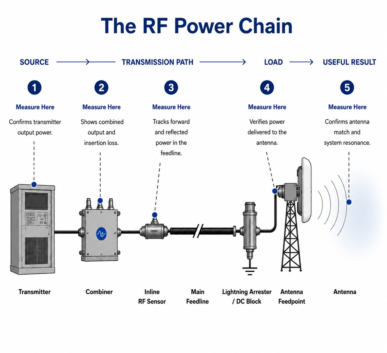
When engineers troubleshoot an RF system, it's easy to think in terms of individual components - the transmitter, the feedline, the antenna, or the load. But RF power doesn't experience the system as a collection of parts. It follows a path.
Bird Technologies calls this path the RF Power Chain.
Every RF system - regardless of application, frequency, or power level - follows the same fundamental sequence:
 The hardware changes from one application to another, but the flow of RF power does not.
Whether you're operating a public safety repeater, driving a plasma chamber in a semiconductor fab, exciting an MRI coil, or transmitting a radar pulse, RF power always follows the same journey. It is generated, transported, delivered, and ultimately converted into useful work.
| Application | Source | Transmission Path | Load | Useful Result |
|---|---|---|---|---|
| Wireless Communications | Transmitter | Feedline & Connectors | Antenna | Radiated Coverage |
| Semiconductor Plasma | RF Generator | Feedline & Matching Network | Plasma Chamber | Process Energy |
| MRI Imaging | RF Amplifier | Transmission Components | RF Coil | Patient Excitation |
| Radar / Defense | Transmitter | Waveguide / Feedline | Antenna | Radiated Pulse |
| Industrial RF Heating | RF Generator | Matching Network | Applicator | Process Heat |
Why the RF Power Chain Matters
The RF Power Chain isn't simply a map of where RF power flows. It is a diagnostic framework for understanding where performance changes occur.
Every measurement gains meaning because of where it is made within the chain.
A power measurement at the transmitter output answers a different engineering question than a power measurement at the antenna. An inline sensor installed after a combiner answers a different question than an antenna sweep. None of these measurements is inherently better than another -they each describe a different part of the system.
Key Insight
Every RF measurement answers a different engineering question. An RF measurement describes conditions only at the point where it is taken. The usefulness of that measurement is determined not by the instrument, but by the engineering question you're trying to answer.
An RF measurement describes conditions only at the point where it is taken. It cannot, by itself, describe the health of the entire RF system.
The value of a measurement is determined by the question you're trying to answer.
| Measurement Location | Engineering Question It Answers |
|---|---|
| Source output | Is the transmitter producing the expected RF power? |
| Transmission Path | Where are losses, reflections, or mismatches being introduced? |
| Load input | Is the intended RF power actually reaching the load? |
| At the load | Is the load efficiently converting RF power into useful work? |
Every RF measurement answers one local engineering question. The challenge isn't collecting more measurements - it's understanding which question each measurement can answer and which questions it cannot. Viewed together across the RF Power Chain, those measurements reveal where the system is performing as expected and where it isn't.
The Transmission Path: Where Most Problems Hide
To see how the RF Power Chain applies in practice, let's focus on the Transmission Path - the part of the system where RF power is transported from the source to the load. Although every RF application uses different hardware, the Transmission Path is almost never a single component. It is a series of cables, connectors, protective devices, sensors, and other hardware, each introducing its own losses, failure modes, and potential measurement locations.
The remainder of this article focuses on the licensed land mobile and professional mobile radio (PMR) transmission path specifically — not because the principles are unique to that application, but because it represents one of the most complete and physically demanding expressions of the signal path model. Long outdoor feedline runs, multi-transmitter combining, weather-exposed connectors, and antenna systems that must perform reliably across an entire licensed band make the land mobile path a useful reference case. Engineers and technicians working in other RF environments will recognize the equivalent components in their own systems.
In licensed land mobile and critical communications infrastructure, the transmission path is not a single element — it is a chain of discrete physical components, each one a potential measurement location and a potential failure point. Not every installation is identical, but the following chain is representative of what technicians encounter in the field.
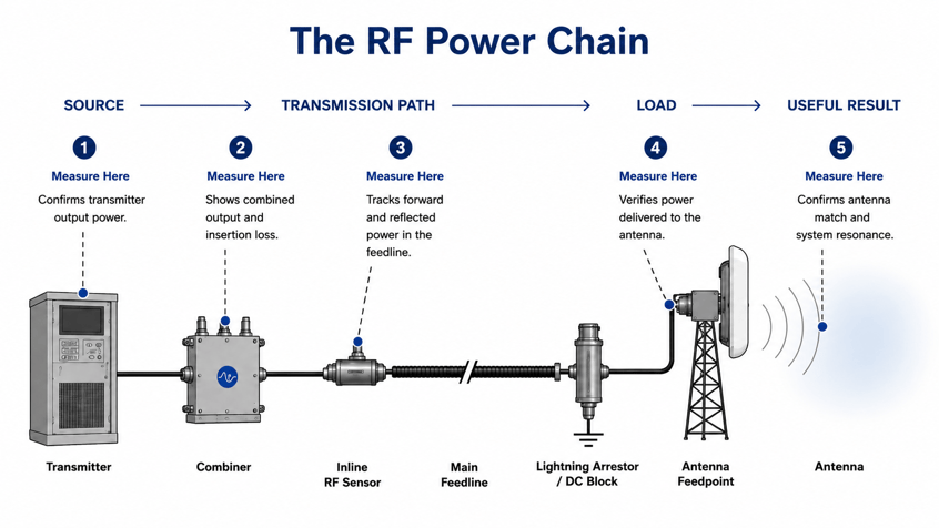
| Component | Role in Signal Path | Key Failure Mode | Measurement Implication |
|---|---|---|---|
| Combiner (where used) | Combines multiple transmitters onto one feedline | Tuning drift increases loss; poor port isolation | Transmitter-end readings do not reflect combiner loss |
| Inline RF Sensors | Monitor forward & reflected power at combiner ports | Sensor drift or miscalibration | Reference point for delivered power calculation |
| Jumper Cable | Flexible connection from transmitter to feedline entry | Connector damage; bend radius violations | Start fault isolation here — easiest to swap |
| Lightning Arrestor / DC Block | Grounds lightning transients; blocks DC | Wrong impedance (75 Ω in 50 Ω system); wrong orientation | Impedance mismatch at a critical junction — hard to detect without inline analyzer |
| Main Feedline | Primary RF run from cabinet to antenna | Moisture ingress; aging; jacket damage | Loss increase is fixed and cannot be corrected by raising power |
| Connectors | Interface between every cable and component | Oxidation; improper installation; inadequate weatherproofing | 6 pairs × 0.2 dB degradation = 1.2 dB total — >20% power loss |
| Weatherproofing | Seals connectors against moisture ingress | Skipped or rushed application | Primary defence against the most common degradation root cause |
| Antenna | Converts conducted RF to radiated signal | Resonant frequency drift; radome damage | Invisible to spot-frequency VSWR — requires full-band sweep |
Every component listed above is a discrete segment of the transmission path — and a discrete measurement opportunity. A reading taken at the transmitter output tells you about the transmitter output. A reading taken at the antenna feed point tells you about the antenna feed point. Neither reading automatically describes what is happening at the connectors, the polyphaser, or anywhere along the feedline run between them.
This is why the component chain matters. Not because each element needs to be measured at every maintenance visit, but because knowing what is in the path — and where each element sits within the RF Power Chain model — allows a technician to ask the right question: at which point in this specific chain is the most useful measurement located for the problem I am trying to solve?
That question — asked before the instrument is connected — is the difference between measurement and diagnosis.
Four Questions Every RF Measurement Should Answer
Before drawing conclusions from any RF measurement, experienced RF professionals ask four questions. These are not procedural steps — they are a mindset. The difference between collecting data and diagnosing a system often comes down to whether these questions are asked before the measurement is interpreted.
| # | Question | What It Reveals |
|---|---|---|
| 1 | Where was the measurement taken? | A measurement provides visibility only at the location where it was collected. Some problems are obvious from one location and invisible from another. |
| 2 | What signal is being measured? | Different signal types create different operating conditions and require different measurement approaches. The signal often determines whether a measurement tells the full story. |
| 3 | What has changed? | A single measurement is a snapshot. Comparing measurements over time reveals trends. In many RF systems, trends are more valuable than absolute values. |
| 4 | What question does the measurement actually answer? | Every measurement has a purpose. Problems arise when a measurement is assumed to answer questions beyond its intended scope. A passing result does not indicate a healthy system — only that a specific parameter is within range. |
These four questions do not require additional equipment or more complex procedures. They require a habit of thinking about measurements as evidence within a system context rather than as standalone facts. That habit is the most transferable skill in RF troubleshooting.
Measuring Is Not the Same as Diagnosing
Measurement and diagnosis are related activities, but they are not the same activity.
Measurement is the collection of data. Diagnosis is the interpretation of that data within the context of system behavior. A measurement can be performed correctly and still produce the wrong conclusion if it does not address the underlying problem.
Likewise, an experienced RF professional can often identify the source of a problem with relatively few measurements — because those measurements are selected deliberately and interpreted within the context of the entire signal path. The selection is as important as the execution.
This distinction separates routine testing from effective troubleshooting. Routine testing confirms that specific parameters are within range. Effective troubleshooting answers the question that actually matters: what is the system actually doing, and why is it not performing as expected?
Field Reality
Every standard check can be performed correctly — forward power, VSWR, reflected power — and all three logged as passing. If those measurements do not cover the part of the system where the problem exists, the log entry is accurate and the conclusion is wrong. Both things are true at the same time.
Looking Ahead
The technician in our opening example did not make a measurement error. The power reading was correct. The VSWR reading was correct. The reflected power reading was correct. The conclusion was wrong.
The measurements answered the question: "Is the transmitter operating normally?" The actual problem lay elsewhere in the signal path. Understanding why that happens — and how measurement location, signal type, and system context all affect what a reading actually means — is the foundation of everything that follows in this series.
In the next article, we examine one of the most trusted measurements in RF maintenance — VSWR — and and explore why a good VSWR reading can sometimes be the first sign that a system is getting worse rather than better. It is one of the most counterintuitive failure modes in RF infrastructure, and it catches experienced technicians as often as it catches novices.
Next in this series - Part 2 of 7: Why a Good VSWR Reading Can Mean Your System Is Getting Worse
About the Author
Katie Wright is an electrical engineer with more than 30 years of experience in RF test and measurement. She specializes in high-power RF measurement, product strategy, and technical thought leadership. During her time at Bird, she wrote about RF measurement accuracy, calibration, and the applications of high-power RF systems. She is also a licensed amateur radio operator (KD8FAD).