How Do Directional Couplers Impact RF Power Measurement Accuracy?
September 24th, 2025
4 min. read | By Katie Wright
Topics:
Directional couplers directly affect RF power measurement accuracy because their coupling factor, directivity, frequency response, linearity, and thermal stability determine how faithfully the sampled signal represents the true mainline power. Errors in any of these parameters can easily add 5–10% uncertainty — even when the downstream instrument is properly calibrated.
Why Couplers Matter in RF Power Measurement?
Couplers are sampling devices: they extract a fraction of the RF signal for analysis while letting the mainline power continue to the load. Accuracy depends on the quality of that sample. If a coupler drifts, saturates, or suffers from poor directivity, it introduces error that propagates to every downstream sensor, analyzer, or scope.
In the sections that follow, we’ll examine different coupler designs, the five key parameters that directly affect measurement accuracy, and real-world examples of how coupler performance can make or break an RF test.
Coupler Design: Ferrite vs. Air-Dielectric
Not all couplers are created equal. The choice of design — typically ferrite-based or air-dielectric — determines how well the device maintains linearity, stability, and accuracy under real-world conditions. Each approach brings trade-offs in cost, size, and performance, and understanding those trade-offs is essential before selecting a coupler for precision RF power measurement.
- Ferrite-Based Couplers
- Compact and relatively inexpensive.
- Suitable for many CW monitoring applications.
- Limitations: ferrite saturation under high fields, temperature-dependent performance, degraded accuracy for pulsed signals.
- Air-Dielectric Couplers
- Excellent linearity and stability across power levels.
- Preferred for precision measurements, especially in pulsed or reflective environments.
- Limitations: physically larger, more fragile, higher cost.
Technical Deep Dive
Ferrite couplers couple energy magnetically, which keeps size small but introduces nonlinearity at high fields. Once ferrite materials saturate, the coupling factor drifts, causing errors of 5–10% in pulsed or radar applications. They also suffer from thermal drift, as ferrite permeability changes with temperature.
Air-dielectric couplers, on the other hand, use transmission-line techniques that remain linear and stable across wide power and temperature ranges. Though bulkier, they are the preferred choice in environments like semiconductor fabs or radar ranges, where ±1–3% accuracy is required.
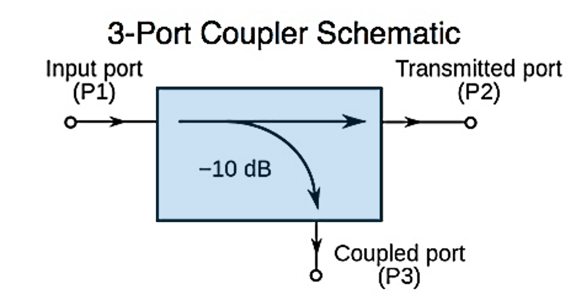
Directional vs. Non-Directional Couplers
Not all couplers provide directional information. The distinction between directional and non-directional couplers is critical for engineers who need accurate forward and reflected power data.
- Non-Directional Couplers
- Sample the total RF signal without distinguishing between forward and reflected components.
- Simpler and sometimes lower-cost.
- Adequate for applications where only total line power is needed.
- Limitation: Cannot separate incident and reflected waves, making them unsuitable for return loss, VSWR, or reflection-sensitive measurements.
- Directional Couplers
- Sample only the forward or the reflected wave, depending on orientation.
- Provide true separation of incident and reflected power.
- Enable critical measurements like return loss, VSWR, and reflection coefficient.
- Slightly more complex design, but essential for precision RF work.
Technical Deep Dive
The physics is rooted in wave superposition. In a transmission line, the forward and reflected waves combine to create the total voltage/current seen at a point. A non-directional coupler samples this sum, giving no visibility into reflections. Directional couplers use phasing and geometry to cancel either the forward or reflected component, isolating the wave of interest. This isolation — called directivity — is what allows engineers to quantify mismatch loss, optimize impedance, and troubleshoot reflections. Without it, “measured power” is really just an average of incident and reflected energy, which hides the true performance of the system.
Engineering takeaway ⚡
If your application involves antennas, plasma processes, radar, or any mismatched load, a non-directional coupler can mask critical problems. Directional couplers are the only choice when forward/reflected accuracy and system efficiency matter.
5 Parameters That Impact RF Accuracy
1. Coupling Factor Accuracy
-
- Nominal values (e.g., 20 dB) rarely match reality.
- A 0.5 dB error equates to ~12% power error.
- Best practice: use calibration data, not just datasheet values.
The coupling factor is frequency- and temperature-dependent. In practice, each coupler’s actual factor is characterized during calibration. If engineers assume the nominal value without applying calibration coefficients, every downstream measurement carries systematic bias. This becomes critical when comparing measurements across labs or over time.
2. Directivity
-
- Poor directivity (<25 dB) lets forward energy leak into reflected measurements.
- High-directivity couplers (≥40 dB) provide cleaner forward/reflected separation.
Directivity defines how well a coupler isolates ports. Low directivity means crosstalk contaminates reflected readings, especially in high-VSWR systems like plasma chambers or mismatched antennas. This leakage often produces optimistic return loss numbers, masking real issues.
3. Frequency Response
-
- Coupling factors vary across frequency bands.
- A coupler accurate at 500 MHz may drift by several dB at 2 GHz.
Frequency flatness is limited by the coupler’s design (broadband vs. narrowband). Transmission-line couplers maintain flatter response, while ferrite-based devices often show ripple across frequency. If a test spans multiple bands (e.g., cellular + WiFi + radar), ignoring this ripple can inflate uncertainty.
4. Linearity & Power Handling
-
- At high fields, nonlinearities distort the sample.
- Always rate couplers above peak envelope power (PEP), not just CW average.
Couplers exposed to radar or pulsed RF must handle PEPs orders of magnitude above average power. Nonlinearities appear first as harmonic distortion in the sampled path, then as outright saturation. Engineers often assume “CW rating” equals safe operation, but under pulsed conditions, errors compound quickly.
5. Thermal & Mechanical Stability
-
- Heat, torque, and connector wear shift impedance.
- Stable results require torque wrenches and temperature-compensated designs.
At high duty cycles, couplers act like resistive loads — they heat, expand, and detune. Even connector torque plays a role: under- or over-tightening subtly shifts return loss. Over time, mechanical stress and connector wear introduce uncertainty that calibration cannot always compensate.
Real-World Impact Examples
Couplers aren’t just passive plumbing — the wrong choice can create errors that ripple through an entire measurement system. Here are a few real-world cases where coupler selection makes or breaks accuracy:
|
Use Case |
Problem with Poor Coupler |
Solution with Proper Coupler |
|
Semiconductor Fabs |
Low-directivity couplers misreport reflected power during plasma ignition, leading to false indications of chamber drift. |
High-directivity directional couplers cleanly separate forward/reflected waves, ensuring process stability is measured accurately. |
|
Radar Systems |
Ferrite couplers saturate at high peak envelope power, flattening pulses and hiding overshoot, droop, or compression. |
Air-dielectric couplers handle high PEP without saturation, preserving pulse fidelity for calibration and compliance. |
|
Antenna Testing |
Frequency ripple and poor directivity distort VSWR and return-loss results, masking mismatches and causing mistuned deployments. |
Broadband, high-directivity couplers reveal true reflections, ensuring efficient antenna design and reliable field performance. |
|
RF Generator Calibration |
Non-directional couplers mask reflected energy, leading to over- or under-calibration of generator output power. |
High-directivity directional couplers measure forward power correctly, making generator calibration traceable and repeatable. |
Closing Thought
Directional couplers are not interchangeable plumbing. They are precision devices that establish the accuracy floor of every RF power measurement. Unlike non-directional couplers, which only show total line power, directional couplers provide the forward and reflected data needed to calculate return loss, VSWR, and true system efficiency. A poor coupler can introduce more uncertainty than the best power sensor can eliminate. For engineers who need trustworthy numbers, the choice of coupler — and its calibration — is as critical as the instrument it feeds.
Katie Wright is an electrical engineer with more than 30 years of experience in RF Test & Measurement, specializing in high-power RF measurement, product strategy, and technical thought leadership. Throughout her career, she has worked closely with engineers and customers across the semiconductor, aerospace & defense, broadcasting, and industrial markets to translate complex RF technologies into practical engineering knowledge. Her work focuses on RF measurement accuracy, calibration, and helping engineers better understand the principles and applications behind high-power RF systems.
Explore Posts by Topic:
Products Featured:
Contact an RF Expert at Bird
Connect with a solutions expert for knowledgeable guidance.


