Attenuators and couplers don’t directly measure RF power — but they are critical components that make accurate measurements possible. Attenuators safely reduce high-power signals so sensors can handle them, while couplers sample a small fraction of the signal to provide forward and reflected power data. Both methods have been used for decades, and each comes with trade-offs in accuracy, calibration requirements, and application fit.
Attenuators and Couplers have been workhorses for decades — simple, effective, and still relevant in labs and field applications. But while both methods are familiar, they also come with accuracy challenges engineers can’t afford to ignore.
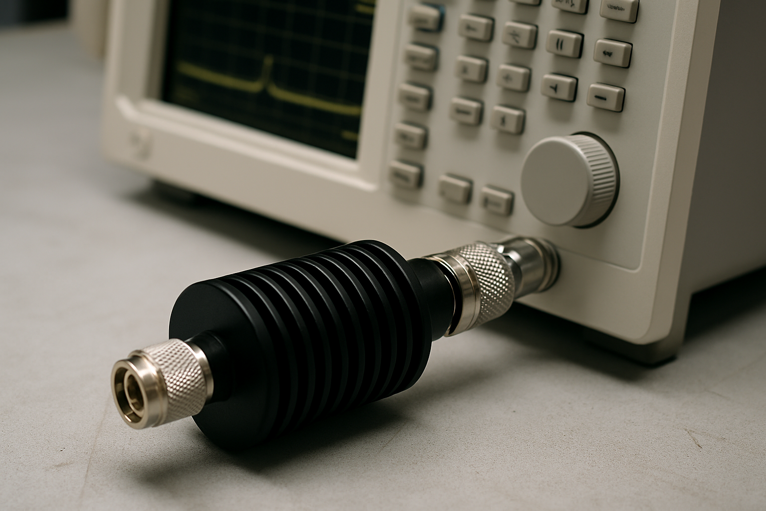
High-Power Attenuator + Power Sensor
This is one of the simplest and most common setups for handling very high power RF levels.
How it works:
- A calibrated attenuator reduces the signal’s amplitude before sending it to a terminating power sensor.
- Most of the energy is dissipated as heat, while the sensor measures the scaled-down signal.
- The true RF power is calculated by applying the attenuation factor.
Strengths
- Safely handles hundreds or thousands of watts.
- Wideband capability across MHz to GHz.
- Rugged and durable for lab and transmitter testing.
Limitations
- Thermal drift: attenuation changes as components heat.
- Bulky: often requires active cooling.
- Forward only: no reflection data.
- Pulse fidelity: peaks are smoothed, hiding true values.
Engineering takeaway ⚡
Best suited for controlled lab environments or high-power transmitter testing but requires frequent recalibration. Without it, error margins can creep above 10%.
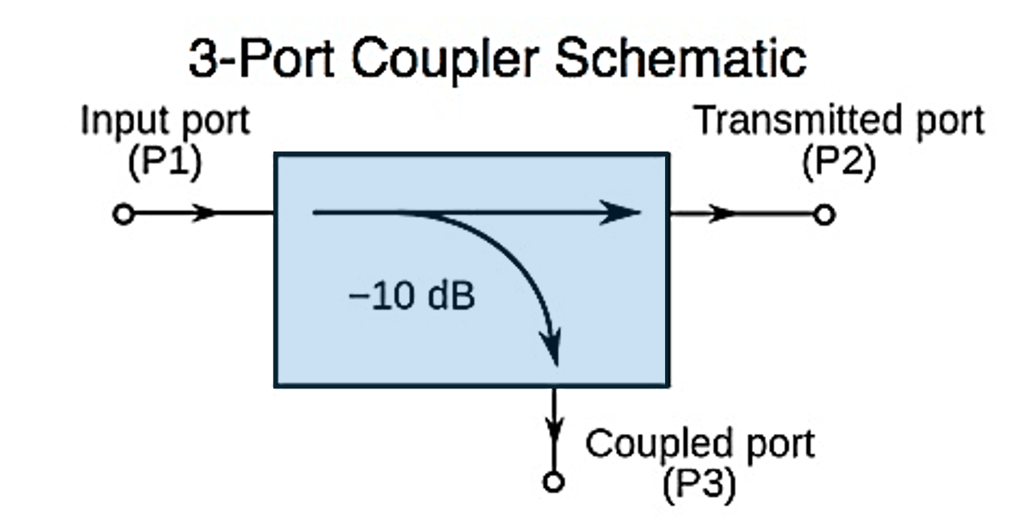
Directional Coupler + Terminating Power Sensor
In this setup, a coupler samples a small portion of the RF signal and routes it to a terminating power sensor. Engineers can measure either forward or reflected power depending on coupler orientation.
Strengths
- Enables measurement of both forward and reflected power.
- Supports return loss and VSWR calculations.
- Minimal disruption to the system under test.
- Wide frequency coverage depending on design.
Limitations
- Mismatch sensitivity degrades accuracy in high-reflection conditions.
- Calibration complexity — both coupler and sensor need regular recalibration.
- Poor pulsed accuracy due to bandwidth limits.
- Thermal drift affects coupling factor under high power.
Engineering takeaway ⚡
A flexible method for CW measurements and monitoring, but not recommended for precision pulsed RF. Treating the coupler as “transparent” is a common mistake.
Comparing the Two Approaches
|
Method
|
Best Use Case
|
Strengths
|
Limitations
|
|
High-Power Attenuator + Sensor
|
High-power transmitters, calibration labs
|
Rugged, handles very high power
|
Bulky, thermal drift, no reflection data
|
|
Directional Coupler + Sensor
|
CW monitoring, VSWR/return loss
|
Forward + reverse power, broad frequency coverage
|
Sensitive to mismatch, poor pulsed accuracy
|
Closing Thought
Attenuators and couplers remain fundamental RF power measurement tools. But accuracy depends on how well you manage their limitations. Understanding their strengths and limitations helps engineers choose the right setup — and avoid accuracy pitfalls.
👉 Resources for You:
In our next post, we’ll answer another key question: Can oscilloscopes and spectrum analyzers measure RF power accurately?
Katie Wright
Katie Wright has more than 30 years of experience in RF Test & Measurement, specializing in high-power RF measurement, product strategy, and technical thought leadership. Throughout her career, she has worked closely with engineers and customers across the semiconductor, aerospace & defense, broadcasting, and industrial markets to translate complex RF technologies into practical engineering knowledge. Her work focuses on RF measurement accuracy, calibration, and helping engineers better understand the principles and applications behind high-power RF systems.


