Master the measurements that keep your system performing.
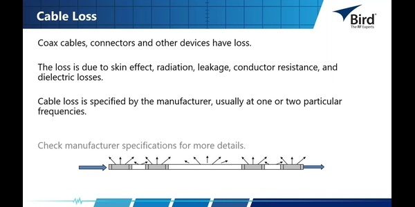
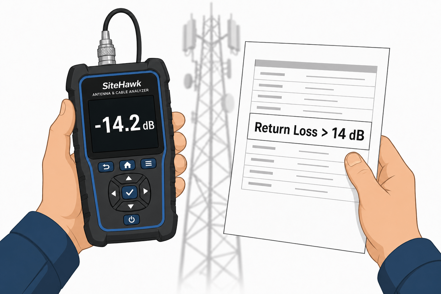
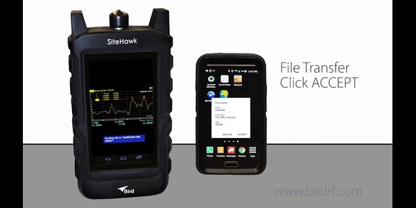
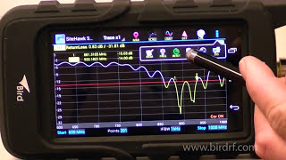
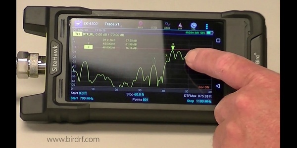
In this webinar, Bird’s engineers share the essentials of cable and antenna testing with the SiteHawk, giving you the tools to troubleshoot faster and keep systems online.
You’ll learn:
-
Key measurements – How to quickly identify and solve common problems
-
RF basics for troubleshooting – Understanding what the readings mean
-
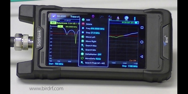
Analyzer features – Getting the most from your Cable & Antenna Analyzer
-
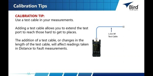
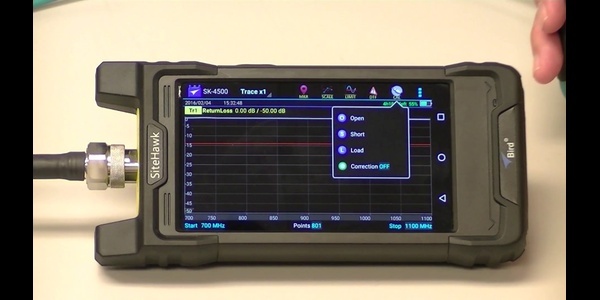
Calibration essentials – Why it matters and how to do it right
Perfect for technicians and engineers who want to reduce downtime, improve accuracy, and extend the life of their RF systems.
Frequently Asked Questions About Cable and Antenna Testing
How do you test a cable and antenna system?
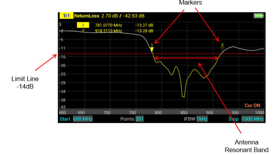
To test a cable and antenna system, disconnect it from the transmitter and connect a calibrated cable and antenna analyzer to the feed line. Sweep the system’s operating frequency range to measure VSWR or return loss and identify impedance mismatches. Cable loss and distance-to-fault measurements can then help evaluate signal loss and locate faults along the transmission line. For example, a system operating from 440–470 MHz might be tested to confirm that VSWR remains below 1.5:1 across the entire band.
How often should antenna systems be tested?
There is no universal testing schedule for antenna systems. Testing frequency should be based on system criticality, operating environment, maintenance requirements, and manufacturer recommendations. Mission-critical or outdoor systems may benefit from periodic testing because weather, corrosion, cable damage, and connector degradation can affect RF performance over time. For example, a critical communications site may be tested on a scheduled maintenance interval and again after severe weather, equipment changes, or suspected performance issues.
What equipment do you need to test an antenna?
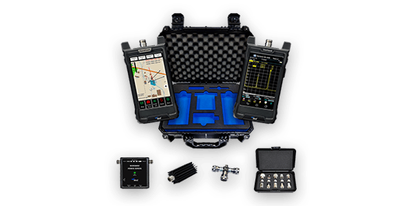
Antenna testing typically requires a cable and antenna analyzer that covers the antenna’s operating frequency range. The test setup may also include a calibrated test cable, the correct adapters, and calibration standards for accurate VSWR, return loss, cable loss, and distance-to-fault measurements. For example, a technician might use a handheld cable and antenna analyzer covering 100 MHz–6 GHz to measure VSWR and return loss at the antenna feed point.
Bird Applications Team
Applied RF know-how from Bird engineers—field-tested techniques, measurement methods, and troubleshooting.