
Using Plasma Process Fingerprinting to Improve Yield
August 4th, 2026
4 min. read | By Nik Azim
Topics:
Monitor plasma in real time to create accurate process models.
What You'll Learn:
- Why conventional 50 Ω RF measurements can't characterize plasma
- How to create a plasma process fingerprint
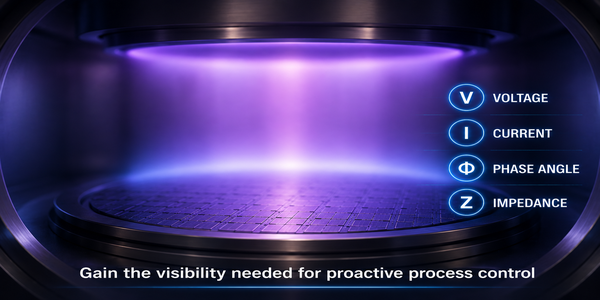
- Which electrical measurements define the fingerprint
- How V-I-phase measurements improve process control
- How the Bird BDS2 detects process drift
As semiconductor geometries continue to shrink, process windows become increasingly narrow. Small changes in plasma behavior can shift recipe steps outside acceptable tolerances, affecting repeatability and ultimately yield.
Recipes for a particular wafer define the steps required to construct the semiconductor wafer. As wafers become more complex and have smaller geometries, the tolerance range on recipe steps gets tighter. Uniformity of a deposited film, film stress, film depth, and etch endpoints are critical parameters that require tight control. Maintaining these process recipe steps within their defined tolerances maximizes yield. Controlling these processes requires monitoring the state of the plasma during all recipe steps.
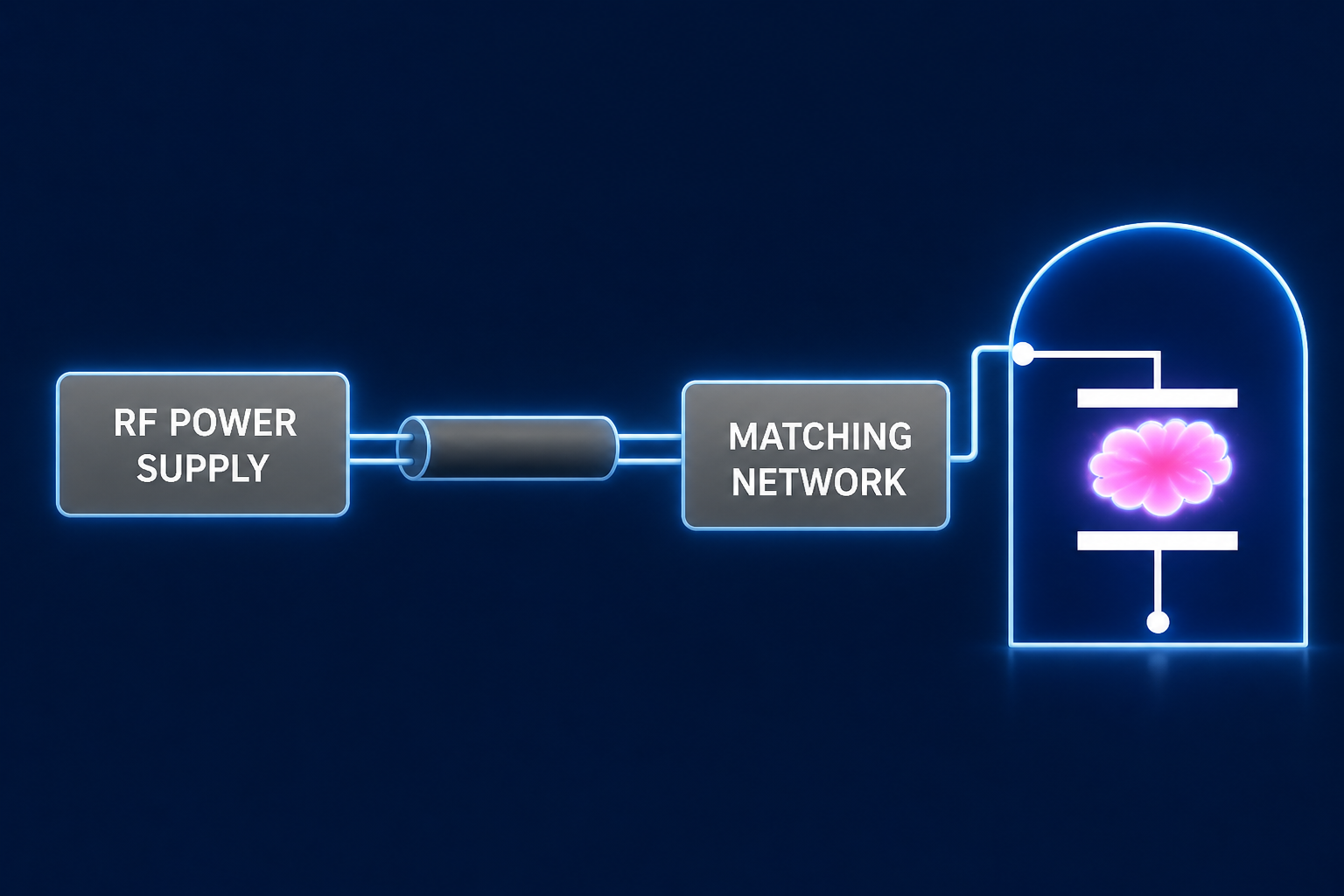
One problem is that plasma is a partially ionized gas containing electrons, ions, radicals, and excited molecules. Sustained by RF energy, plasma acts simultaneously as a chemical reactor and as the load for the RF circuit. Plasma is a nonlinear, time-varying impedance and is highly sensitive to operating conditions. Conventional RF power sensors are designed to measure forward and reflected power in transmission lines with a 50 Ω characteristic impedance. While these measurements are ideal for generator calibration and RF delivery verification before the matching network, they do not directly characterize the complex, time-varying impedance of the plasma after the match network.
The second problem is correlating information on the plasma during the different recipe steps to changes in physical control parameters such as chemical gas flow, chamber temperature, and chamber pressure. Also, the condition of the plasma chamber, the deposits on the chamber walls, is a factor that affects plasma impedance.
The solution is creating a process fingerprint of the plasma as a function of recipe steps by relating changes in physical parameters to changes in the plasma. Once a process fingerprint has been established, subsequent runs can be compared against the baseline to detect subtle process drift before wafer yield is affected. That requires a methodology to measure plasma in real time during processing.
Creating the Process Fingerprint
During process development, engineers intentionally vary parameters such as RF power, chamber pressure, and temperature to understand how the plasma responds. By correlating electrical measurements with wafer inspection results, process recipes are developed that define acceptable operating ranges which can be used to identify signs of process drift.
Measurements Needed for Plasma Impedance Monitoring
Among the many plasma process objectives that must be managed are process repeatability, plasma stability, product yield, endpoint consistency, and chamber health. A valuable electrical parameter for characterizing plasma is impedance, which is calculated from measured voltage, current, and phase. Additionally, because plasma behaves as a nonlinear load, monitoring its harmonic content provides further insight into plasma changes. Together, these measurements quantify the electrical signature required to establish a process recipe’s fingerprint, which is central to process control.
Bird's Solution – a Smart Plasma Impedance Meter
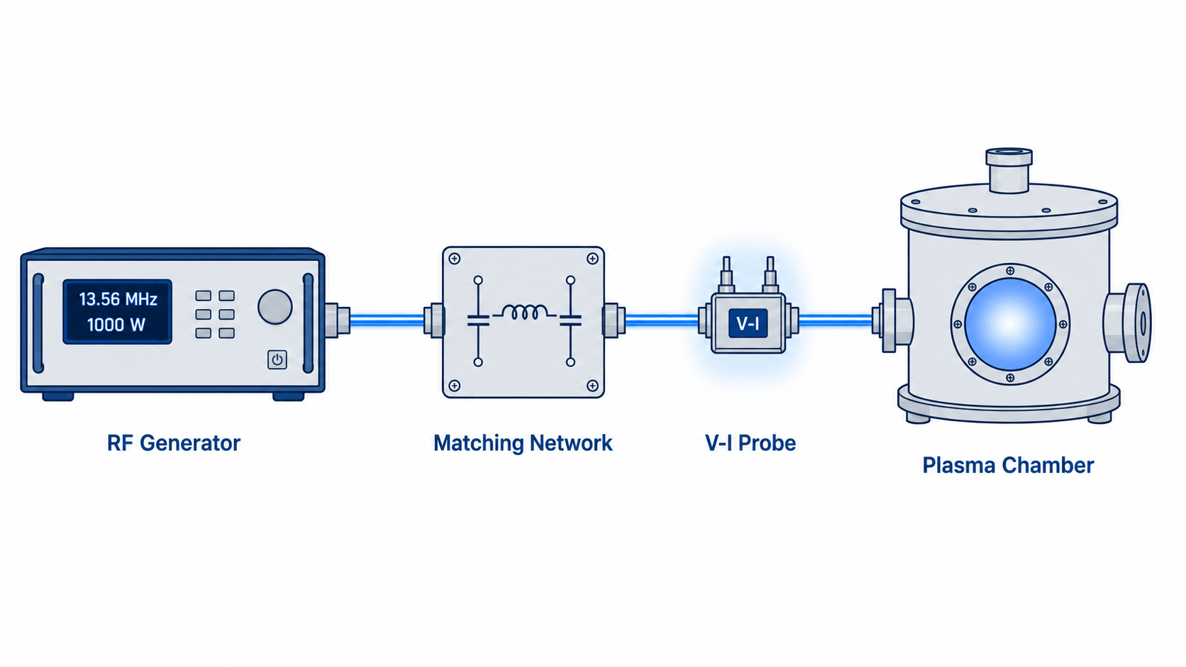
Monitoring the plasma requires an instrument that can measure the non-50 Ω environment created by the plasma. The BDS2 Bird Diagnostic System Inline Voltage and Current Probe combines an RF sensor placed at the entrance to the plasma chamber with a remote receiver. The instrument has the following capabilities:
- Measurement of voltage, current, and phase, then calculation of impedance, return loss, and reflection coefficient across fundamental, harmonic, and intermodulation components
- Captures up to three fundamentals simultaneously, four harmonics per fundamental, and six intermodulation products per fundamental pair, with harmonic content available up to 252 MHz
- Measurement of multi-level pulse or CW waveforms with a frequency-tracking algorithm that holds accuracy under dynamic signal conditions
- Displays the voltage, current, phase, power, or impedance from a pulsed RF waveform with the optional time-domain mode
- Provides high accuracy of up to 1% of reading for voltage and current at the fundamental in a locked system, with a 95% confidence interval
- Ethernet-enabled for integration into tool control schemes supporting chamber-to-chamber matching, RF process monitoring, impedance matching, and identifying process drift
The measurements derived from the BDS2 create the fingerprint that can be used to monitor and control the recipe for a specific process.
Conclusion: Building a Plasma Process Fingerprint to Maximize Yield
Creating an electrical fingerprint of plasma processes provides engineers with a baseline for maintaining process repeatability, plasma stability, product yield, endpoint consistency, and chamber health across multiple tools. By measuring voltage, current, and phase of fundamental and harmonic signals directly at the chamber, engineers gain the visibility needed to maximize yield while reducing troubleshooting time.
Process fingerprinting gives semiconductor engineers an objective way to detect drift before it affects wafer quality. By measuring the electrical behavior of the plasma, not just generator output, you gain the visibility needed to improve repeatability, optimize recipes, and maintain yield across production tools.
Need help selecting the right plasma measurement approach? Contact Bird to discuss your application.
Frequently Asked Questions
Why can't I rely on the RF generator's power reading?
Because what the generator reports is not what reaches the plasma. The generator measures power as it leaves its output, assuming a fixed 50 Ω system. Between the generator and the chamber, the match network, cables, and connectors add losses and reflections that reduce the delivered power. The plasma itself is a non-linear, time-varying load, not the 50 Ω load the generator is designed to power. So, the generator's forward-power reading describes what it sends, not what the plasma absorbs.
Where should I measure plasma RF power, before or after the match box?
After the match box, as close to the chamber input as practical. The match network transforms the plasma's variable impedance toward 50 Ω so the generator sees a stable load. That means any measurement taken upstream reflects generator-side conditions, not delivery to the plasma. Measuring after the match box captures the voltage, current, and phase that the plasma actually sees, which is the data needed for process control.
What is a process fingerprint?
A process fingerprint is a recorded electrical signature of the plasma across a recipe's steps. It maps measured parameters (voltage, current, phase, impedance, and harmonic content) against time and against physical control parameters like gas flow, chamber pressure, and temperature. Once you establish a baseline fingerprint for a successful, high-yield run, you can detect drift, identify deposition or etch endpoints, and trace an out-of-tolerance parameter back to a likely root cause. Fingerprints also support repeatability across tools in one facility and across facilities.
What can the BDS2 measure that a conventional 50 Ω instrument cannot?
The BDS2 measures directly in the non-50 Ω environment that the plasma creates, where conventional instruments designed for 50 Ω systems do not provide valid measurements. It measures RF voltage, current, and phase, then calculates impedance and power at the fundamental, plus up to four harmonics per fundamental and six intermodulation products per fundamental pair. A conventional 50 Ω wattmeter or sensor reports forward and reflected power calibrated for a system with a 50 Ω characteristic impedance, so it cannot represent the plasma's true impedance or its harmonic structure.
Nik is a Product Manager at Bird, focusing on our Precision RF Power Sensor and Precision V-I-Φ Measurement product offerings. These solutions encompass Bird’s most advanced and accurate measurement devices and are utilized in semiconductor fabs and foundries worldwide.
Explore Posts by Topic:
Products Featured:
Contact an RF Expert at Bird
Connect with a solutions expert for knowledgeable guidance.