
Choose the right RF measurement approach to achieve consistent yield across multiple plasma tools.
What You'll Learn:
- Why RF power consistency matters across multiple plasma tools
- What each measurement point actually tells you
- The advantages and limitations of five monitoring strategies
- How to choose the right level of RF measurement for your process
As semiconductor devices become increasingly complex and feature sizes shrink, plasma processes such as chemical vapor deposition and plasma etch demand tighter control to ensure satisfactory yield. While ensuring a single tool successfully completes its recipe steps is straightforward, verifying that multiple tools consistently produce the same results is a more complex challenge.
Verifying RF power delivery and analyzing plasma impedance signatures across various processes and tools is central to determining if a fleet of tools is operating consistently. The considerations semiconductor process and equipment engineers need to make are how many measurements and what type of measurements their systems require to achieve and exceed target yields across the facility.
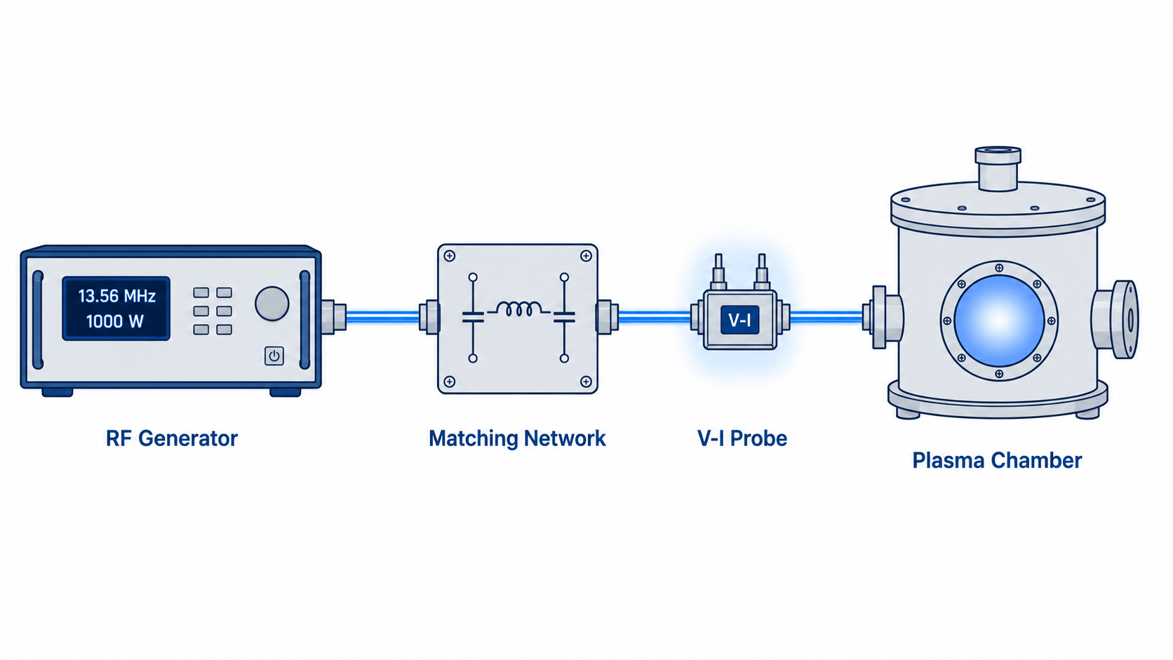
This blog offers a range of options for quantifying the health of the RF generation subsystem (Figure 1) and monitoring chamber impedance to assess plasma status. The options provide varying degrees of visibility into a tool for process monitoring, along with their tradeoffs. Your best option will depend on the complexity of the semiconductor wafers you manufacture. The more closely you monitor each tool, the greater the likelihood that all the tools in the fleet will produce similar results, allowing you to achieve the target yields for the process.
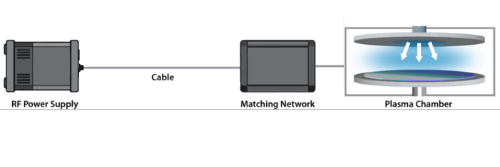
Figure 1. The RF power delivery circuit
Option 1: Periodic calibration of RF power at the match network input
- Technique: On a scheduled basis, use a high-accuracy calibration system to measure the RF power delivered to the match network on every tool.
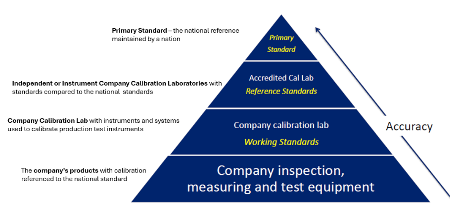
- Benefit: High-accuracy reference standards establish a common measurement baseline across the facility, allowing RF generators to be calibrated to the same traceability path and improving tool-to-tool consistency in RF power delivery
- Limitation: Captures the performance of the RF generation sub-system only at scheduled inspection and calibration intervals. Also, RF power measurements at the matching network do not provide information on the electrical behavior at the plasma chamber interface or on plasma conditions during process steps.
Option 2: Continuous monitoring at the match network input
- Technique: Add a high-accuracy in-line power sensor that continuously measures forward and reflected power, paired with periodic generator calibration on the manufacturer's schedule.
- Benefit: Reports the actual power delivered to the match network, not just the power reported by the generator at its output connector. The power sensor also acts as an independent second monitor. It can immediately indicate an out-of-tolerance condition in the power generation network, allowing engineers to correct the problem before it causes a damaging process variation.
- Limitation: Provides no information on the power delivered to the plasma or the condition of the plasma.
Option 3: Continuous plasma impedance measurement
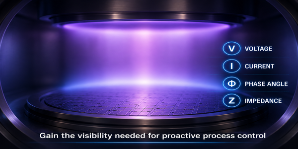
- Technique: At the plasma chamber’s RF interface, utilize a measurement solution capable of measuring the V, I, and Phase of fundamental signals as well as harmonics.
- Benefit: Provides visibility into electrical behavior and plasma impedance at the chamber interface. Furthermore, it lets engineers compare electrical and impedance signatures across tools at each process step to uncover process changes and excursions.
- Limitation: Does not measure the power delivered to the match network, although the generator still reports the power it supplies.
Option 4: Continuous measurements on both sides of the match network
- Technique: Combine an in-line high-accuracy power sensor at the match network input with a V-I probe at the chamber entrance.
- Benefit: Gives continuous feedback on the power delivery, covering both the pre-match 50 Ω path and the post-match plasma chamber. In addition, the measurement at the inlet to the plasma chamber contributes impedance and harmonic data on the plasma.
- Limitation: More information adds some complexity to system control.
Option 5: Continuous V, I, phase, and harmonics measurements on both sides of the match network
- Technique: Place a V-I probe and instrument before the match network and at the chamber entrance.
- Benefit: Provides the most comprehensive electrical characterization of both the RF delivery path and the plasma load throughout the process. The measurements furnish the most information for modeling and controlling the process.
In the 50 Ω pre-match path, the V-I measurement reports RF power and path impedance, which can indicate cable and connector degradation, and it detects harmonic content in the pre-match path. While harmonic levels are typically low in modern semiconductor RF generators, abnormal harmonic content may indicate generator performance issues or nonlinear behavior elsewhere in the RF system.
The V-I measurement at the plasma entrance monitors plasma impedance and harmonic content as previously described.
- Limitation: While this option offers the most information to enable the tightest control tolerances across all tools, it is the highest cost option for each tool.
Solutions from Bird Technologies
Bird brings decades of experience in high-accuracy, high-power measurement for semiconductor manufacturing. Three product families map directly to the options above (Figure 2):
- Portable calibration carts built for clean room use: The Metrology-Grade Calibration Carts provide Bird’s trusted accuracy with high-accuracy sensors, matched loads, and flexible connectivity in a mobile platform. The calibration carts enable verification and adjustment of RF system calibration directly at the process tool.
- High-accuracy in-line RF power sensors for 50 Ω systems: The Precision RF Power Sensor Family includes ±3%, ±1%, and ±0.5% accuracy sensors with NIST-traceable calibration. They accurately measure both CW and multi-level pulsed RF power levels.
- A V-I probe for the non-50 Ω, nonlinear plasma environment: The BDS2 Bird Diagnostic System In-Line Voltage and Current Probe measures voltage, current, and phase to calculate impedance and power. The instrument resolves up to three fundamental frequencies, each with up to four harmonics, for monitoring the plasma state. Furthermore, the BDS2 can quantify power and impedance for fundamentals and harmonics in 50 Ω RF paths.
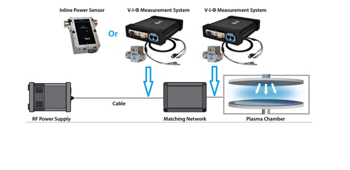
Figure 2. Instrumentation for continuous monitoring — Options 4 or 5
Conclusion: Achieving Consistent RF Power Delivery
Measurements made before the matching network primarily assess the health and performance of the RF delivery system. Measurements made at the chamber entrance primarily assess the electrical behavior of the plasma load. Together, these complementary measurements provide engineers with a more complete understanding of both equipment condition and process performance.
Poor yield is a high-cost problem. Process and equipment engineers need to control their processes to maximize yields. To enable control, the options provide methods to monitor the process with increasing levels of detail. As wafer designs advance with smaller dimensions, the control challenge becomes much greater. With more complex wafers, monitoring the process more comprehensively with real-time measurements, both external to and internal to the chamber, allows engineers to control power delivery and detect variations in plasma impedance. Unlike open-loop operation, feedback from continuous measurements can prevent process excursions that cause yield to plummet across all plasma processing tools. Process and equipment engineers need to determine the trade-off between increased monitoring and feedback on their fleet of tools and the risk of poor yield. Appropriate monitoring for the type of wafer being produced yields a substantial return on investment. Incomplete information increases the risk of low yields and defective, high-cost wafers.
Contact an RF Expert at Bird
Connect with a solutions expert for knowledgeable guidance.