Ethernet RF Monitoring Sensors
Ethernet RF sensors are the foundation of modern RF remote monitoring. Installed directly in the RF path, they provide ongoing visibility into system performance and deliver near real-time measurements and alarms from remote sites to operations teams over standard Ethernet networks.
They help system managers detect change earlier, reduce reactive truck rolls, and maintain confidence in system health between site visits.

How Ethernet RF Sensors Work
Ethernet RF sensors measure RF performance at critical points in the system and make that data accessible over the network. Using standard Ethernet connectivity, measurements can be viewed through a web interface, integrated into SNMP-based monitoring systems, or displayed in a network operations center.
This provides ongoing visibility between site visits, helping teams track how RF conditions change over time—especially at remote or unmanned sites.

Why Ethernet Sensors Matter in Critical Communications

RF degradation is often silent until it impacts users

Receive-side issues may not trigger immediate alarms

Transmit-only monitoring can mask developing problems

Reactive truck rolls increase cost and downtime

Monitoring Roles Supported by Ethernet Sensors
Ethernet RF sensors can monitor different parts of an RF system, depending on site design and maintenance goals.
Start by choosing what you want to monitor—transmit path, receive path, or both—to identify the right sensor.
Transmit Path Monitoring
Verifies transmitter output and tracks forward/reflected power and VSWR at the measurement point
Composite & Multi-Channel Monitoring
Provides visibility into combined or multi-carrier RF signals measured at a single point in the RF path.
Receive Path Monitoring
Helps detect gradual degradation in receive antennas and feedlines—changes that may not be obvious until coverage or sensitivity is affected.
Ethernet RF Sensors by What You Monitor

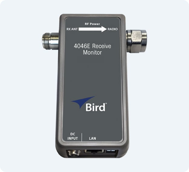
Receive Path Ethernet RF Sensor
4046E - NEW!
Monitors receive-path health at the antenna/feedline to help catch gradual degradation early.
Best for: Proactive receive-path maintenance

Channelized Ethernet RF Sensor
4042E
Provides per-channel transmit visibility to spot changes on individual carriers.
Best for: Multi-channel transmit systems

Channelized Ethernet RF Sensor (PTT-Enabled)
4042E-PTT
Adds PTT-driven alarming and I/O so alarms trigger only during active transmit
Best for: Conventional / trunked PTT systems

Directional Ethernet RF Sensor
4043E
Measures forward/reflected power and VSWR for monitoring combined transmit signals at a single point in the RF path.
Best for: Composite transmit measurement.
Find the Right Ethernet RF Sensor
Use our Sensor Selector to compare Ethernet RF sensor models by monitoring role and application.
How to Choose the Right Ethernet RF Sensor
Not every team starts with a fully defined monitoring plan. The right sensor depends on a few practical questions:
Is monitoring needed at a single site, or across multiple remote sites?
What part of the RF path matters most—transmit, receive, or both?
How many channels (carriers) need to be monitored?
Do you need basic visibility, or PTT-based/context-aware alarming and I/O?
Compare Ethernet RF Monitoring Approaches
Ethernet RF sensors support different monitoring roles depending on your system design and what you need to see. Use the guide below to match your monitoring goal to the right sensor approach.
Ethernet RF Sensor FAQs
Have more questions? Get Expert Help>
Do Ethernet RF sensors replace field testing?
No. Field testing is still essential for installation, validation, and troubleshooting. Ethernet RF sensors provide continuous visibility between site visits, helping identify changes early and prioritize where field testing is needed.
How do I know whether I need channelized, directional, or receive monitoring?
It depends on which part of the RF system you need the most visibility into.
-
Channelized monitoring provides per-channel transmit visibility (ideal when you need to see individual carriers, not just a combined signal).
-
Directional monitoring provides composite transmit measurements (forward/reflected power and VSWR) at a single point in the RF path.
-
Receive-path monitoring focuses on the receive antenna/feedline, helping detect gradual degradation that may not be obvious in transmit metrics or alarms.
Share a few details about your site, and Bird can help confirm the best-fit approach
Do I need to monitor every transmitter individually?
Not always. Some sites get the visibility they need with composite (directional) monitoring, while others benefit from per-channel (channelized) monitoring to isolate issues on individual carriers. The right level of detail depends on system complexity, operational risk, and how quickly you need to pinpoint problems.
Will Ethernet RF monitoring add complexity to my workflow?
Typically, no. Ethernet RF sensors are designed to fit into existing network environments using standard web interfaces and SNMP-based tools. Once configured, teams can monitor sites remotely and receive alarms through their existing workflows with minimal added overhead.
Do I need a full monitoring plan before contacting Bird?
No. If you share your site configuration and goals, we’ll help define the right approach and sensor options.