
Search for topics or resources
Enter your search below and hit enter or click the search icon.

Compare Bird RF loads by power rating, frequency range, cooling method, and connector type to identify the right termination for your RF system. From low-power bench testing to high-power continuous-duty applications, this guide helps you narrow your options based on the electrical, thermal, and installation requirements that matter most.
RF loads convert absorbed RF energy into heat. Power level, operating duration, available cooling, and installation environment all influence how that heat must be dissipated. Compare the cooling methods below to determine which approach best fits your application.
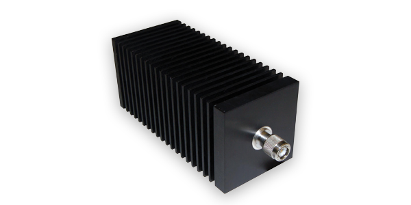
Uses natural airflow to dissipate heat without fans or external cooling.
Best for: Lower-power applications where simple, passive cooling is preferred.
Consider: Requires adequate airflow around the load.
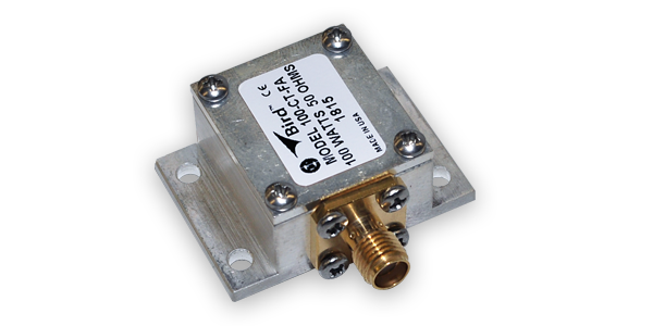
Transfers heat into a mounting surface, heat sink, or system chassis.
Best for: Compact or integrated systems with an available thermal-management surface.
Consider: Requires proper mounting to dissipate heat effectively.
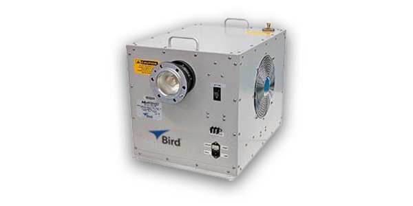
Uses powered airflow to increase heat dissipation and support higher power levels.
Best for: Higher-power or continuous-duty applications where liquid cooling isn't practical.
Consider: Requires electrical power and active airflow.
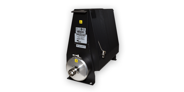
Uses dielectric oil to absorb and transfer heat away from the RF load element.
Best for: Higher-power applications requiring greater heat dissipation without a water supply.
Consider: Larger and heavier than many air-cooled options.
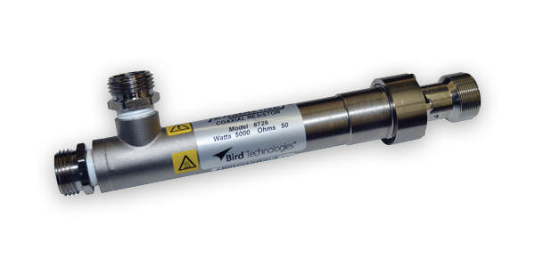
Uses circulating water to efficiently remove heat generated by absorbed RF power.
Best for: High-power, continuous-duty applications with an available water supply.
Consider: Requires adequate water flow and cooling infrastructure.
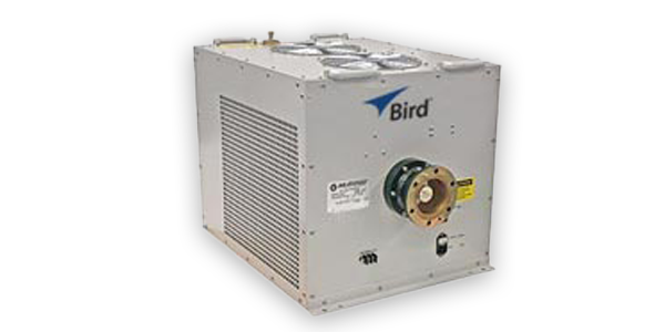
Self-contained RF load systems designed for high-power applications.
Best for: High-power transmitter testing requiring an integrated load system.
Consider: Requires more installation space than a basic RF termination.
Showing 1 - 12 of 177 results
To ensure performance and safety, match the load to your system’s specs and environment.

Frequency Range:
Power Rating
VSWR
Peak-to-Average Ratio

Connector or flange type
Cooling method (air, water, oil)
Mounting and space constraints

Ambient temperature, coolant flow/quality
Shock, vibration, altitude, and humidity tolerance
Not sure which power rating, cooling method, frequency range, or configuration is right for your application? Bird's RF experts can help you evaluate your requirements and identify the right load for your system.