Compare Bird RF attenuators by attenuation value, power rating, frequency range, and cooling method to identify the best solution for your RF application. Whether you're testing equipment, integrating RF systems, or protecting sensitive instruments, this guide helps you narrow your options and find the attenuator that meets your requirements.
Selecting the right RF attenuator starts with understanding your application. Define these four requirements first to narrow your options before comparing models. New to RF terminology? Explore our RF Engineering Glossary.
How much must the RF signal be reduced before it reaches your equipment?
How much transmitter power will the attenuator absorb without overheating?
Will the attenuator operate across your required frequency range?
How will the attenuator connect to your RF system?
Once you've defined your attenuation, power, frequency, and connector requirements, the next consideration is how the attenuator manages the heat generated by the power it dissipates.
Cooling method affects power handling, duty cycle, size, maintenance, and installation requirements. The required power level often determines the appropriate cooling method. Compare the differences below to see when convection-cooled and oil-cooled attenuators are typically used.
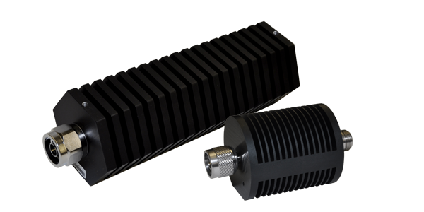
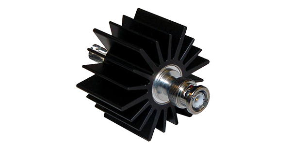
Best for: Low to medium power RF applications
Cooling Method: Heat is dissipated through external heatsinks using natural airflow.
Advantages
Considerations
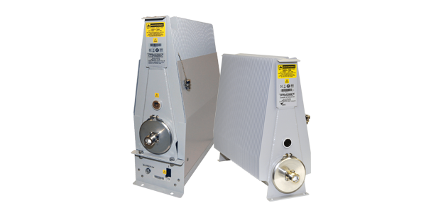
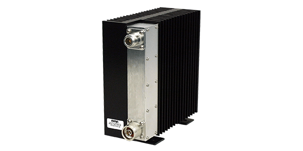
Best for: Medium to high power RF applications
Cooling Method: Dielectric oil absorbs heat from the resistive element and transfers it throughout the enclosure for efficient cooling.
Advantages
Considerations
Now it's time to narrow your options. Use the filters below to compare Bird RF attenuators by power rating, attenuation, and frequency range to identify the model that best fits your application.
Showing 1 - 12 of 144 results
Have more questions? Get Expert Help>
Signal attenuation is measured as the loss of signal power between two points, expressed in decibels (dB) by comparing input vs. output levels.
For example, if a signal drops from +50 dBm (100 W) to +47 dBm, that is 3 dB attenuation (~50% power loss); a drop to +40 dBm is 10 dB attenuation (~90% loss).
Instruments like VNAs or spectrum analyzers measure this across frequency (e.g., –1 dB at 1 GHz vs. –3 dB at 3 GHz), while high-power attenuators are used to safely handle and measure these losses in systems carrying 1 W to several kW, ensuring accurate readings without damaging test equipment.
Lower attenuation is usually better if your goal is to deliver as much power as possible.
Lower attenuation means less signal loss. For example, 1 dB (~20% loss) is much better than 3 dB (~50%) or 10 dB (~90%). However, higher attenuation is often used intentionally in RF systems, such as adding 20–30 dB attenuation to safely reduce a +50 dBm (100 W) signal down to a level a spectrum analyzer can handle (-10 dBm to 0 dBm).
Choose an RF attenuator in two steps.
First, determine the attenuation level needed and frequency. For example, 10 dB (~90% reduction) or 30 dB (~99.9%) to reduce a +50 dBm (100 W) signal to 0–20 dBm, and ensure it covers your band (e.g., DC–3 GHz or up to 6+ GHz).
Second, select the cooling method based on power: convection-cooled for low-moderate power (1–1000 W) or oil-cooled for high power (100 W to multi-kW).
Every RF system is different. If you're unsure which attenuation value, power rating, frequency range, or connector configuration you need, our applications team can help you choose the right Bird attenuator for your system.